
Instruction manual


6 - 111
6 POSITIONING CONTROL
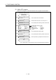
[Cautions]
(1) The number of control axes cannot be changed during control.
(2) The speed-switching point can be specified the absolute data method (VABS)
and incremental data method (VINC) by mixed use.
(3) The speed-switching point cannot be specified an address which change in travel
direction. If the travel direction change, the error code [215] is stored in the minor
error storage register for each axis and the deceleration stop is performed.
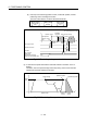
(4) It checks whether to be the end address within the stroke limit range at the start.
If it is positioning to outside the stroke limit range, the error code [106] is stored in
the minor error storage register for each axis and operation does not start.
(5) If the travel value between speed-switching points is so short and it shifts to the
next speed-switching point during speed-switching control, the speed-switching
does not perform.
(6) The M-code from the previous point is retained in the point with which M-code is
not specified.
[Program]
Program for speed-switching is shown as the following conditions.
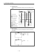
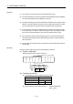
(1) System configuration
Speed-switching control of Axis 2 and Axis 3.
Q61P Q03UD
CPU
Q172D
CPU
Q172D
LX
QY41
MM MM
Motion CPU control module
Start command (PX000)
Axis
4
Axis
1
Axis
2
Axis
3
AMP AMP AMP AMP
QX41
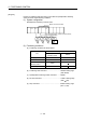
(2) Positioning conditions
(a) Speed-switching control conditions are shown below.
Item Setting
Servo program No. 500
Control axis Axis 2 Axis 3
End address 100000 50000
(b) Speed-switching control start command ....... PX000 Leading edge
(OFF
ON)