
Instruction manual

5 - 24
5 SERVO PROGRAMS FOR POSITIONING CONTROL
(1) Word devices for indirect setting data
The devices for indirect setting data are the data registers (D), link registers (W),
motion registers (#) and Multiple CPU area device (U
\G). Word devices except
the above devices cannot be used.
The usable setting range of word devices is shown below.
Word device Setting range
D 800 to 8191
W 0 to 1FFF
# 0 to 7999
U \G 10000 to (10000+p-1)
(Note-1)
(Note-1): "p" indicates the user setting area points of the Multiple CPU high speed transmission area for
the each CPU.
ABS-3
Axis 1,
Axis 2,
Axis 3,
Vector speed
Dwell
M-code
P.B.
Positioning
data
<K 11>
D3000
D3004
W010
40000.00
W1B0
D3600
3
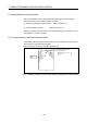
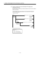
Indirect setting by word device
Execute the positioning control by the data of
(D3001, D3000), (D3005, D3004), (W11, W10),
W1B0 and D3600.
Numerical value setting
Axis No. cannot be set indirectly by word device.
Fig. 5.4 Example of indirect setting by word device for positioning data
(2) Bit devices for indirect setting data
The devices for indirect setting data are the input (X), output (Y), internal relay
(M), link relay (B), annunciator (F) and Multiple CPU area device (U
\G).
Bit devices except the above devices cannot be used.
The usable setting range of bit devices is shown below.
Bit device Setting range
X 0000 to 1FFF
Y 0000 to 1FFF
M 0 to 8191
B 0000 to 1FFF
F 0 to 2047
U \G 10000.0 to (10000+p-1).F
(Note-1)
(Note-1): "p" indicates the user setting area points of the Multiple CPU high speed transmission area for
the each CPU.