
Instruction manual


11 - 14
11. OPTIONS AND AUXILIARY EQUIPMENT
(2) Wires for cables
When fabricating a cable, use the wire models given in the following table or equivalent:
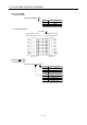
Table 11.1 Wires for option cables
Characteristics of one core
Type Model
Length
[m(ft)]
Core
size
[mm
2
]
Number
of
Cores
Structure
[Wires/mm]
Conductor
resistance
[
/km]
Insulation coating
ODd[mm]
(Note 1)
(Note 3)
Finishing
OD[mm]
Wire model
0.2
2
(1 pairs)
40/0.08
(Note 4)
105 or less
0.88 10.5
0.3
2
(1 pairs)
3/20/0.08
(Note 4)
71.9 or less
1.3 10.5
MR-JRCBL M-H
2 to 30
(6.56 to 98.4)
0.5
6
(3 pairs)
3/33/0.08
(Note 4)
43.5 or less
1.53 10.5
(Note 2)
J14B1180
0.2
2
(1 pairs)
40/0.08
(Note 4)
105 or less
0.08 10.5
0.3
2
(1 pairs)
3/20/0.08
(Note 4)
71.9 or less
1.3 10.5
2 to 30
(6.56 to 98.4)
0.5
6
(3 pairs)
3/33/0.08
(Note 4)
43.5 or less
1.53 10.5
(Note 2)
J14B1180
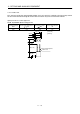
Motor
cable
MR-JRBRCBL
M-H
0.2 (0.66) 0.5
1
(Single
wire)
20/0.18 36.7 2.6 2.6
UL1015
AWG#20
MR-JRPC98CBL3M
Communi-
cation
canble
MR-JRPCATCBL3M
3 (9.84) 0.08
6
(3 pairs)
7/0.127 222 or less 0.38 4.6
UL20276
AWG#28 3pair
(BLACK)
MR-J2HBUS M
MR-J2HBUS M-A
20
(10 pairs)
6.1
UL20276
AWG#28 10pair
(CREAM)
Q172J2BCBL M
Bus cable
Q173J2B
CBL M
0.5 to 5
(1.64 to 16.4)
0.08
14
(7 pairs)
7/0.127 222 or less 0.38
5.5
UL20276
AWG#28 7pair
(CREAM)
Note 1: d is as shown below:
d
Conductor Insulation sheath
2: Purchased from Junkosha
3: Standard OD. Max OD is about 10% greater.
4. Measurement condition 20
(68 )