General-Purpose AC Servo J2-Jr Series General-Purpose Interface Compatible MODEL MR-J2-03A5 SERVO AMPLIFIER INSTRUCTION MANUAL C
z Safety Instructions z (Always read these instructions before using the equipment.) Do not attempt to install, operate, maintain or inspect the servo amplifier and servo motor until you have read through this Instruction Manual, Installation guide, Servo motor Instruction Manual and appended documents carefully and can use the equipment correctly. Do not use the servo amplifier and servo motor until you have a full knowledge of the equipment, safety information and instructions.
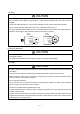
1. To prevent electric shock, note the following: WARNING y Before wiring or inspection, switch power off and wait for more than 15 minutes. Then, confirm the voltage is safe with voltage tester. Otherwise, you may get an electric shock. y Connect the servo amplifier and servo motor to ground. y Any person who is involved in wiring and inspection should be fully competent to do the work. y Do not attempt to wire the servo amplifier and servo motor until they have been installed.
. Additional instructions The following instructions should also be fully noted. Incorrect handling may cause a fault, injury, electric shock, etc. (1) Transportation and installation CAUTION y Transport the products correctly according to their masses. y Stacking in excess of the specified number of products is not allowed. y Do not carry the servo motor by the cables, shaft or encoder. y Do not hold the front cover to transport the servo amplifier. The servo amplifier may drop.
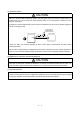
(2) Wiring CAUTION y Wire the equipment correctly and securely. Otherwise, the servo motor may misoperate. y Do not install a power capacitor, surge absorber or radio noise filter between the servo motor and servo amplifier. y Connect the output terminals (U, V, W) correctly. Otherwise, the servo motor will operate improperly. y Do not connect AC power directly to the servo motor. Otherwise, a fault may occur.
(5) Corrective actions CAUTION y When it is assumed that a hazardous condition may take place at the occur due to a power failure or a product fault, use a servo motor with electromagnetic brake or an external brake mechanism for the purpose of prevention. y Configure the electromagnetic brake circuit so that it is activated not only by the servo amplifier signals but also by an emergency stop. EMG Servo amplifier Circuit must be opened during emergency stop.
About processing of waste When you discard servo amplifier, a battery (primary battery), and other option articles, please follow the law of each country (area). FOR MAXIMUM SAFETY These products have been manufactured as a general-purpose part for general industries, and have not been designed or manufactured to be incorporated in a device or system used in purposes related to human life.
COMPLIANCE WITH EC DIRECTIVES 1. WHAT ARE EC DIRECTIVES? The EC directives were issued to standardize the regulations of the EU countries and ensure smooth distribution of safety-guaranteed products.
(5) Auxiliary equipment and options (a) The circuit protector used should be the EN or IEC Standard-compliant product of the model described in Section 12.2.2. (b) The sizes of the cables described in Section 12.2.2 meet the following requirements. To meet the other requirements, follow Table 5 and Appendix C in EN60204-1.
CONTENTS 1. FUNCTIONS AND CONFIGURATION 1- 1 to 1- 6 1.1 Introduction ・・・・・・・・・・・・・・・・・・・・・・・・・・・・・・・・・・・・・・・・・・・・・・・・・・・・・・・・・・・・・・・・・・・・・・・・・・・ 1.2 Servo Amplifier Standard Specifications ・・・・・・・・・・・・・・・・・・・・・・・・・・・・・・・・・・・・・・・・・・・・・・・・・・ 1.3 Function List ・・・・・・・・・・・・・・・・・・・・・・・・・・・・・・・・・・・・・・・・・・・・・・・・・・・・・・・・・・・・・・・・・・・・・・・・・・ 1.4 Model Code Definition ・・・・・・・・・・・・・・・・・・・・・・・・・・・・・・・・・・・・・・・・・・・・・・・・・・・・・・・・・・・・・・・・・・ 1.
4. OPERATION 4- 1 to 4- 6 4.1 When Switching Power On for the First Time ・・・・・・・・・・・・・・・・・・・・・・・・・・・・・・・・・・・・・・・・・・・・・ 4.2 Startup・・・・・・・・・・・・・・・・・・・・・・・・・・・・・・・・・・・・・・・・・・・・・・・・・・・・・・・・・・・・・・・・・・・・・・・・・・・・・・・・ 4.2.1 Selection of control mode ・・・・・・・・・・・・・・・・・・・・・・・・・・・・・・・・・・・・・・・・・・・・・・・・・・・・・・・・・・・・ 4.2.2 Position control mode・・・・・・・・・・・・・・・・・・・・・・・・・・・・・・・・・・・・・・・・・・・・・・・・・・・・・・・・・・・・・・・・ 4.2.3 Speed control mode ・・・・・・・・・・・・・・・・・・・・・・・・・・・・・・・・・・・・・・・・・・・・・・・・・・・・・・・・・・・・・・・・・ 4.2.
7.3 Gain Adjustment by Auto Tuning ・・・・・・・・・・・・・・・・・・・・・・・・・・・・・・・・・・・・・・・・・・・・・・・・・・・・・・・・ 7- 5 7.3.1 Adjustment method ・・・・・・・・・・・・・・・・・・・・・・・・・・・・・・・・・・・・・・・・・・・・・・・・・・・・・・・・・・・・・・・・・ 7- 5 7.3.2 Valid conditions・・・・・・・・・・・・・・・・・・・・・・・・・・・・・・・・・・・・・・・・・・・・・・・・・・・・・・・・・・・・・・・・・・・・・ 7- 5 7.4 Manual Gain Adjustment ・・・・・・・・・・・・・・・・・・・・・・・・・・・・・・・・・・・・・・・・・・・・・・・・・・・・・・・・・・・・・・・ 7- 6 7.4.1 When machine rigidity is low・・・・・・・・・・・・・・・・・・・・・・・・・・・・・・・・・・・・・・・・・・・・・・・・・・・・・・・・・ 7- 6 7.4.
12.2.3 Relays ・・・・・・・・・・・・・・・・・・・・・・・・・・・・・・・・・・・・・・・・・・・・・・・・・・・・・・・・・・・・・・・・・・・・・・・・・・ 12- 13 12.2.4 Noise reduction techniques ・・・・・・・・・・・・・・・・・・・・・・・・・・・・・・・・・・・・・・・・・・・・・・・・・・・・・・・ 12- 13 12.2.5 Snubber unit ・・・・・・・・・・・・・・・・・・・・・・・・・・・・・・・・・・・・・・・・・・・・・・・・・・・・・・・・・・・・・・・・・・・・ 12- 17 13. COMMUNICATION FUNCTIONS 13- 1 to 13- 26 13.1 Configuration ・・・・・・・・・・・・・・・・・・・・・・・・・・・・・・・・・・・・・・・・・・・・・・・・・・・・・・・・・・・・・・・・・・・・・・・・ 13- 1 13.1.
Optional Servo Motor Instruction Manual CONTENTS The rough table of contents of the optional MELSERVO Servo Motor Instruction Manual is introduced here for your reference. Note that the contents of the Servo Motor Instruction Manual are not included in the Servo Amplifier Instruction Manual. 1. INTRODUCTION 2. INSTALLATION 3. CONNECTORS USED FOR SERVO MOTOR WIRING 4. INSPECTION 5. SPECIFICATIONS 6. CHARACTERISTICS 7. OUTLINE DIMENSION DRAWINGS 8.
MEMO
1. FUNCTIONS AND CONFIGURATION 1. FUNCTIONS AND CONFIGURATION 1.1 Introduction The MELSERVO-J2-Jr series general-purpose AC servo has been developed as an ultracompact, small capacity servo system compatible with the MELSERVO-J2 series 24VDC power supply. It can be used in a wide range of fields from semiconductor equipment to small robots, etc. The input signals of the servo amplifier control system are compatible with those of the MR-J2-A.
1. FUNCTIONS AND CONFIGURATION 1.2 Servo Amplifier Standard Specifications Servo Amplifier MR-J2-03A5 Item Voltage Circuit power supply Power supply capacity HC-AQ0135D HC-AQ0235D HC-AQ0335D Control circuit power supply (Note) Control system 21.6 to 30VDC (instantaneous permissible voltage 34V) Continuous 0.8A, max. 2.4A Continuous 1.6A, max. 4.8A Continuous 2.4A, max. 7.
1. FUNCTIONS AND CONFIGURATION 1.3 Function List The following table lists the functions of the MR-J2-03A5. For details of the functions, refer to the corresponding chapters and sections. Function Description (Note) Control Mode Refer To Position control mode MR-J2-03A5 is used as position control servo. P Section 3.1.1 Section 3.4.1 Section 4.2.2 Speed control mode MR-J2-03A5 is used as speed control servo. S Section 3.1.2 Section 3.4.2 Section 4.2.
1. FUNCTIONS AND CONFIGURATION Description (Note) Control Mode Servo configuration software Using a personal computer, parameter setting, test operation, status display, etc. can be performed. P, S, T Section 12.1.3 Alarm code output If an alarm has occurred, the corresponding alarm number is output in 3-bit code. P, S, T Section 9.2.1 Function Refer To Note.
1. FUNCTIONS AND CONFIGURATION 1.6 Parts Identification Name/Application Display The four-digit, seven-segment LED shows the servo status and alarm number. Refer To Chapter6 Operation section Used to perform status display, diagnostic, alarm and parameter operations. MODE UP DOWN SET Used to set parameter data. Chapter6 Used to change the display or data in each mode. Used to change the mode. I/O signal connector (CN1A) Used to connect digital I/O signals. Section3.
1. FUNCTIONS AND CONFIGURATION 1.7 Servo System with Auxiliary Equipment WARNING y To prevent an electric shock, fit the supplied earth terminal (E) to the servo amplifier (refer to (2), Section 3.9) and always connect it to the earth (E) of the control box.
2. INSTALLATION 2. INSTALLATION CAUTION y Stacking in excess of the limited number of products is not allowed. y Install the equipment to incombustible. Installing them directly or close to combustibles will led to a fire. y Install the equipment in a load-bearing place in accordance with this Instruction Manual. y Do not get on or put heavy load on the equipment to prevent injury. y Use the equipment within the specified environmental condition range.
2. INSTALLATION 2.2 Installation direction and clearances CAUTION y The equipment must be installed in the specified direction. Otherwise, a fault may occur. y Leave specified clearances between the servo amplifier and control box inside walls or other equipment. (1) Installation of one servo amplifier Control box Control box 40mm (1.6 in.) or more Wiring clearance Servo amplifier MITSUBISHI 10mm (0.4 in.) or more OPEN MELSERVO CN1A CNP1 CN1B 10mm (0.4 in.) or more Top 70mm (2.8 in.
2. INSTALLATION 2.3 Keep out foreign materials (1) When installing the unit in a control box, prevent drill chips and wire fragments from entering the servo amplifier. (2) Prevent oil, water, metallic dust, etc. from entering the servo amplifier through openings in the control box or a fan installed on the ceiling.
2. INSTALLATION 2.5 Using the DIN rail for installation (1) Fitting into the DIN rail Put the upper catch on the DIN rail and push the unit until it clicks. Wall Wall Upper catch DIN rail DIN rail (2) Removal from DIN rail 1) Pull down the hook. 2) Pull it toward you. 3) Lift and remove the unit.
3. SIGNALS AND WIRING 3. SIGNALS AND WIRING WARNING y Any person who is involved in wiring should be fully competent to do the work. y Before starting wiring, make sure that the voltage is safe in the tester more than 15 minutes after power-off. Otherwise, you may get an electric shock. y Ground the servo amplifier and the servo motor securely. y Do not attempt to wire the servo amplifier and servo motor until they have been installed. Otherwise, you may get an electric shock.
3. SIGNALS AND WIRING 3.1 Standard connection example POINT y For the connection of the power supply system, refer to Section 3.7.1. y Do not apply the test lead bars or like of a tester directly to the pins of the connectors supplied with the servo motor. Doing so will deform the pins, causing poor contact. 3.1.1 Position control mode AD75P 24VDC power supply (A1SD75P ) Circuit protector Servo amplifier CNP1 RA + P24M 1 − P24G 2 P24L 3 (Note 4,7) CN1A Signal Name Pin No.
3. SIGNALS AND WIRING Note 1. To prevent an electric shock, fit the supplied earth terminal (E) to the servo amplifier and always connect it to the earth (E) of the control box. (Refer to section 3.9.) 2. Connect the diode in the correct direction. If it is connected reversely, the servo amplifier will be Cfaulty and will not output signals, disabling the forced stop and other protective circuits. 3. The forced stop switch must be installed. 4. CN1A and CN1B have the same shape.
3. SIGNALS AND WIRING 3.1.2 Speed control mode 24VDC power supply Circuit protector Servo amplifier CNP1 RA + P24M 1 − P24G 2 P24L 3 (Note 4) CN1B 3 VDD 13 COM 18 ALM RA1 19 ZSP RA2 6 TLC RA3 (Note 4,7) CN1A Speed Selection 1 SP1 8 SG 10 SG 20 (Note 6) Trouble Zero speed Limiting torque 10m (32ft) max.
3. SIGNALS AND WIRING 3.1.3 Torque control mode 24VDC power supply Circuit protector Servo amplifier CNP1 RA + P24M 1 − P24G 2 P24L 3 (Note 4) CN1B (Note 4,6) CN1A Speed Selection 1 SP1 8 SG 10 SG 20 3 VDD 13 COM 18 ALM RA1 19 ZSP RA2 6 TLC RA3 (Note 2) (Note 5) Trouble Zero speed Limiting torque 10m(32ft) max.
3. SIGNALS AND WIRING 3.2 Internal Connection Diagram of Servo Amplifier The following is the internal connection diagram where the signal assignment has been made in the initial status in each control mode. Servo amplifier CNP2 2 CNP1 P24M 1 2 7 V P24L 3 8 W 1 E (Note) P S T CN1B CNP2 VDD VDD VDD 3 3 COM COM COM 13 9 (Note) P U P24G B2 B1 (Note) S T COM COM COM CN1A 9 CR SP1 SP1 8 SG SG SG 10,20 Approx.4.
3. SIGNALS AND WIRING 3.3 I/O Signals 3.3.1 Connectors and signal arrangements POINT The pin configurations of the connectors are as viewed from the cable connector wiring section. Refer to the next page for CN1A and CN1B signal assignment.
3.
3.
3. SIGNALS AND WIRING 3.3.2 Signal explanations For the I/O interfaces (symbols in I/O column in the table), refer to Section 3.6.2. In the Control Mode field of the table P : Position control mode, S: Speed control mode, T: Torque control mode {: Denotes that the signal may be used in the initial setting status. ∆ : Denotes that the signal may be used by setting the corresponding parameter among parameters 43 to 49. The pin No.s in the connector pin No. column are those in the initial status.
3. SIGNALS AND WIRING Signal Torque limit Forward rotation start Reverse rotation start ConnecSymbol tor Pin No. TL ST1 ST2 I/O Division Functions/Applications CN1B 9 Torque limit selection input device. Short TL-SG to make the analog torque limit valid. For details, refer to (2), section 3.4.1.
3. SIGNALS AND WIRING Signal Speed selection 1 ConnecSymbol tor Pin No. SP1 CN1A 8 Functions/Applications Used to select the command speed for operation. (Note) Input signals SP2 SP1 0 0 I/O Division Control Mode P S T DI-1 Speed Command Analog speed command (VC) 0 1 Internal speed command 1 (parameter No. 8) 1 0 Internal speed command 2 (parameter No. 9) 1 1 Internal speed command 3 (parameter No. 10) Note.
3. SIGNALS AND WIRING Signal Proportion control Forced stop Clear Control change ConnecSymbol tor Pin No. PC EMG CR LOP Functions/Applications I/O Division Connect PC-SG to switch the speed amplifier from the proportional integral type to the proportional type. If the servo motor at a stop is rotated even one pulse due to any external factor, it generates torque to compensate for a position shift.
3. SIGNALS AND WIRING Signal Analog torque limit Analog torque command ConnecSymbol tor Pin No. TLA TC Analog speed command VC Analog speed limit VLA Forward rotation pulse train Reverse rotation pulse train CN1B 12 PP NP PG NG CN1B 2 CN1A 3 CN1A 2 CN1A 13 CN1A 12 Functions/Applications I/O Division To use this signal in the speed control mode, set any of parameters No. 43 to 48 to make TL available.
3. SIGNALS AND WIRING (2) Output signals Signal Trouble ConnecSymbol tor Pin No. ALM Functions/Applications I/O Division CN1B 18 ALM-SG are disconnected when power is switched off or the protective circuit is activated to shut off the base circuit. Without alarm, ALM-SG are connected within about 1s after power on. DO−1 RD CN1A 19 RD-SG are connected when the servo is switched on and the servo amplifier is ready to operate.
3. SIGNALS AND WIRING Signal Alarm code ConnecSymbol tor Pin No. ACD0 ACD1 ACD2 CN1A 19 CN1A 18 CN1B 19 I/O Division Functions/Applications To use this signal, set 1 in parameter No. 49. This signal is output when an alarm occurs. When there is no alarm, respective ordinary signals (RD, INP, SA, ZSP) are output. Alarm codes and alarm names are listed below: (Note) Alarm Code Alarm CN1B CN1A CN1A Display 19 Pin 18 Pin 19 Pin 0 0 0 8888 Watchdog A. 11 Board error 1 A. 12 Memory error 1 A.
3. SIGNALS AND WIRING Signal ConnecSymbol tor Pin No. Encoder Z-phase pulse (Open collector) OP Encoder A-phase pulse (Differential line driver) LA LAR CN1A 14 CN1A 6 CN1A 16 Functions/Applications I/O Division Outputs the zero-point signal of the encoder. One pulse is output per servo motor revolution. OP and LG are connected when the zero-point position is reached. ( Negative logic) The maximum pulse width is about 400µs. For zeroing using this pulse, set the creep speed to 100r/min. or less.
3. SIGNALS AND WIRING (3) Power supply Signal ConnecSymbol tor Pin No. Functions/Applications I/O Division Control Mode P S T I/F internal power supply VDD CN1B 3 Used to output 24VDC for input interface. Connected with P24L inside the servo amplifier. { { { Digital I/F power supply input COM CN1A 9 CN1B 13 Used to input 24VDC for input interface. Connect the positive terminal of the 24VDC external power supply.
3. SIGNALS AND WIRING 3.4 Detailed Description of the Signals 3.4.1 Position control mode (1) Pulse train input (a) Input pulse waveform selection Command pulses may be input in any of three different forms, for which positive or negative logic can be chosen. Set the command pulse train form in parameter No. 21. or in the table indicates the timing of importing a pulse train. Arrow A- and B-phase pulse trains are imported after they have been multiplied by 4.
3. SIGNALS AND WIRING (b) Connections and waveforms 1) Open collector system Connect as shown below: Servo amplifier 24VDC P24G P24L VDD OPC PP About 2kΩ NP About 2kΩ SG SD The explanation assumes that the input waveform has been set to the negative logic and forward and reverse rotation pulse trains (parameter No.21 has been set to 0010). The waveforms in the table in (a), (1) of this section are voltage waveforms of PP and NP based on SG.
3. SIGNALS AND WIRING 2) Differential line driver system Connect as shown below: Servo amplifier PP PG NP NG SD The explanation assumes that the input waveform has been set to the negative logic and forward and reverse rotation pulse trains (parameter No.21 has been set to 0010). For the differential line driver, the waveforms in the table in (a), (1) of this section are as follows. The waveforms of PP, PG, NP and NG are based on that of the ground of the differential line driver.
3. SIGNALS AND WIRING (2) Torque limit If the torque limit is canceled during servo lock, the servomotor may suddenly rotate according to position deviation in respect to the command position. CAUTION (a) Torque limit and generated torque By setting parameter No. 28 (internal torque limit 1), torque is always limited to the maximum value during operation. A relationship between the limit value and servo motor-generated torque is shown below. Generated torque Max.
3. SIGNALS AND WIRING (b) Torque limit value selection Choose the torque limit made valid by the internal torque limit value 1 (parameter No. 28) using the external torque limit selection (TL) or the torque limit made valid by the analog torque limit (TLA) as indicated below: Torque Limit Value Made Valid (Note) TL If TLA > Parameter No. 28 If TLA < Parameter No. 28 Internal torque limit value 1 (parameter No. 28) 0 Internal torque limit value 1 (parameter No. 28) 1 Analog torque limit (TLA) Note.
3. SIGNALS AND WIRING 3.4.2 Speed control mode (1) Speed setting (a) Speed command and speed The servo motor is run at the speeds set in the parameters or at the speed set in the applied voltage of the analog speed command (VC).
3. SIGNALS AND WIRING (b) Speed selection 1 (SP1), speed selection 2 (SP2) and speed command value Choose any of the speed settings made by the internal speed commands 1 to 3 using speed selection 1 (SP1) and speed selection 2 (SP2) or the speed setting made by the analog speed command (VC). (Note) External Input Signals SP2 Speed Command Value SP1 0 0 Analog speed command (VC) 0 1 Internal speed command 1 (parameter No. 8) 1 0 Internal speed command 2 (parameter No.
3. SIGNALS AND WIRING 3.4.3 Torque control mode (1) Torque control (a) Torque command and generated torque A relationship between the applied voltage of the analog torque command (TC) and the torque generated by the servo motor is shown below. The maximum torque is generated at ±8V. Note that the torque generated at ±8V input can be changed with parameter No. 26. CCW direction Max. torque Forward rotation (CCW) Generated torque −8 −0.05 +0.05 +8 TC applied voltage [V] CW direction Max.
3. SIGNALS AND WIRING (b) Analog torque command offset Using parameter No. 30, the offset voltage of -999 to +999mV can be added to the TC applied voltage as shown below. Generated torque Max. torque 0 Parameter No.30 offset range −999 to +999mV +8(−8) TC applied voltage [V] (2) Torque limit By setting parameter No. 28 (internal torque limit 1), torque is always limited to the maximum value during operation. A relationship between limit value and servo motor-generated torque is as in (2) in section 3.4.
3. SIGNALS AND WIRING (b) Speed selection 1 (SP1)/speed selection 2 (SP2) and speed command values Choose any of the speed settings made by the internal speed limits 1 to 3 using speed selection 1 (SP1) and speed selection 2 (SP2) or the speed setting made by the speed limit command (VLA). (Note) External Input Signals Speed Command Value SP2 SP1 0 0 Speed limit command (VLA) 0 1 Parameter No. 8 1 0 Parameter No. 9 1 1 Parameter No. 10 Note.
3. SIGNALS AND WIRING 3.4.4 Position/speed control change mode Set 0001 in parameter No. 0 to switch to the position/speed control change mode. This function is not available in the absolute position detection system. (1) Control change (LOP) Use control change (LOP) to switch between the position control mode and the speed control mode from an external contact.
3. SIGNALS AND WIRING (3) Speed setting in speed control mode (a) Speed command and speed The servo motor is run at the speed set in parameter No. 8 (internal speed command 1) or at the speed set in the applied voltage of the analog speed command (VC). A relationship between analog speed command (VC) applied voltage and servo motor speed and the rotation directions determined by the forward rotation start signal (ST1) and reverse rotation start signal (ST2) are as in (a), (1) in section 3.4.2.
3. SIGNALS AND WIRING 3.4.5 Speed/torque control change mode Set 0003 in parameter No. 0 to switch to the speed/torque control change mode. (1) Control change (LOP) Use control change (LOP) to switch between the speed control mode and the torque control mode from an external contact. Relationships between LOP-SG status and control modes are indicated below: (Note) LOP Servo Control Mode 0 Speed control mode 1 Torque control mode Note.
3. SIGNALS AND WIRING (4) Speed limit in torque control mode (a) Speed limit value and speed The speed is limited to the limit value set in parameter No. 8 (internal speed limit 1) or the value set in the applied voltage of the analog speed limit (VLA). A relationship between the analog speed limit (VLA) applied voltage and the servo motor speed is as in (a), (3) in section 3.4.3.
3. SIGNALS AND WIRING 3.4.6 Torque/position control change mode Set 0005 in parameter No. 0 to switch to the torque/position control change mode. (1) Control change (LOP) Use control change (LOP) to switch between the torque control mode and the position control mode from an external contact. Relationships between LOP-SG status and control modes are indicated below: (Note) LOP Servo Control Mode 0 Torque control mode 1 Position control mode Note.
3. SIGNALS AND WIRING 3.5 Alarm Occurrence Timing Chart y When an alarm has occurred, remove its cause, make sure that the operation signal is not being input, ensure safety, and reset the alarm before restarting operation. y As soon as an alarm occurs, turn off Servo-on (SON) and power off the main circuit. CAUTION When an alarm occurs in the servo amplifier, the base circuit is shut off and the servo motor is coated to a stop. Switch off the main circuit power supply in the external sequence.
3. SIGNALS AND WIRING 3.6 Interfaces 3.6.1 Common line The following diagram shows the power supply and its common line. DC24V CNP1 P24G P24L CN1A CN1B CN1A RA CN1B VDD COM DI-1 DO-1 ALM etc. SON etc. SG OPC (Note) PG NG PP NP SG 15VDC±10% 30mA P15R OP Open collector output 35mA or less LG Analog input (+10V/max. current) TLA VC etc. LA etc. Differential line driver output 35mA or less LG LAR etc.
3. SIGNALS AND WIRING 3.6.2 Detailed description of the interfaces This section gives the details of the I/O signal interfaces (refer to I/O Division in the table) indicated in Section 3.3.2. Refer to this section and connect the interfaces with the external equipment. (1) Digital input interface DI-1 Give a signal with a relay or open collector transistor. Servo amplifier 24VDC P24G P24L VDD COM For a transistor R:Approx. 4.7kΩ SON etc. Approx. 5mA Switch SG TR VCES≤1.
3. SIGNALS AND WIRING (3) Pulse train input interface DI-2 Provide a pulse train signal in the open collector or differential line driver system. (a) Open collector system 1) Interface Servo amplifier 24VDC P24G P24L Max. input pulse frequency 200kpps VDD Approx. 1.2kΩ OPC 2m(78.74in) or less PP(NP) Approx. 10mA SG SD 2) Conditions of the input pulse tHL tc PP tLH = tHL < 0.2µs tc > 2µs tF > 3µs 0.9 0.
3. SIGNALS AND WIRING (b) Differential line driver system 1) Interface Servo amplifier Max. input pulse frequency 500kpps 10m (393.70in) or less PP(NP) PG(NG) Am26LS31 or equivalent About 100 SD 2) Conditions of the input pulse tc PP PG tHL tLH tHL 0.1 s tc 1 s tF 3 s 0.9 0.1 tc tLH tF NP NG (4) Encoder pulse output DO-2 (a) Open collector system Interface Max.
3. SIGNALS AND WIRING (b) Differential line driver system 1) Interface Max.output current 35mA Servo amplifier LA (LB,LZ) Servo amplifier LA (LB,LZ) Am26LS32 or equivalent 100Ω High-speed photocoupler 150Ω LAR (LBR,LZR) LG LAR (LBR,LZR) SD SD 2) Output pulse Servo motor CCW rotation LA LAR T LB LBR π/2 LZ LZR 400µs or more Open OP Shorted (5) Analog input Input impedance 10 to 12kΩ Servo amplifier 15VDC P15R 2k Upper limit setting 2k VC‚ etc LG SD 3 - 39 Approx.
3. SIGNALS AND WIRING 3.7 Input Power Supply Circuit CAUTION 3.7.1 y When the servo amplifier has become faulty, switch power off on the servo amplifier power side. Continuous flow of a large current may cause a fire. Connection example Wire the power supply and main circuits as shown below so that the servo-on signal also turns off as soon as power is switched off at detection of alarm occurrence.
3. SIGNALS AND WIRING 3.7.2 Explanation of signals Abbreviation Signal Name P24M Main circuit power input Description Power supply for main circuit P24G Power ground Main circuit power supply and control power supply. Connected to SG and LG inside the unit. P24L Control power input Control power supply and digital I/O power supply. Always use a stabilizing power supply. Grounding terminal Connect to the earth of the control box for grounding. Ground 3.7.
3. SIGNALS AND WIRING (3) Forced stop CAUTION y To stop operation and switch power off immediately, provide a forced stop circuit. Make up a circuit which shuts off main circuit power as soon as EMG-SG are opened at a forced stop. To ensure safety, always install a forced stop switch across EMG-SG. By disconnecting EMG-SG, the dynamic brake is operated to bring the servo motor to a sudden stop. At this time, the display shows the servo forced stop warning (A. E6).
3. SIGNALS AND WIRING 3.8 Servo Motor with Electromagnetic Brake Configure the electromagnetic brake operation circuit so that it is activated not only by the servo amplifier signals but also by an external emergency stop signal. Circuit must be opened during emergency stop signal. EMG Servo amplifier CAUTION Servo motor CNP2 POINT Refer to the Servo Motor Instruction Manual for specifications such as the power supply capacity and operation delay time of the electromagnetic brake.
3. SIGNALS AND WIRING (2) Setting Using parameter No.33 (electromagnetic brake sequence output), set a time delay (Tb) at servo-off from electromagnetic brake operation to base circuit shut-off as in the timing chart shown in (2) in this section. (3) Operation timing (a) Servo-on (SON) command ON/OFF Tb [ms] after the servo-on (SON) signal is switched off, the servo lock is released and the servo motor coasts.
3. SIGNALS AND WIRING (c) Alarm occurrence POINT When the overcurrent(A.32) alarm occurs, the dynamic brake cannot be operated. Dynamic brake Dynamic brake Electromagnetic brake Servo motor speed Base circuit Electromagnetic brake(CNP2-9) Electromagnetic brake ON OFF Invalid(ON) Electromagnetic brake operation delay time(10ms) Valid(OFF) No(ON) Trouble (ALM) Yes(OFF) (d) Main circuit power off When main circuit power switches off, the undervoltage alarm (A.
3. SIGNALS AND WIRING 3.9 Grounding WARNING y Ground the servo amplifier and servo motor securely. y To prevent an electric shock, always connect the earth terminal (E) of the servo amplifier to the earth (E) of the control box (refer to (2) of this section for the fitting method of the earth terminal). (1) Connection diagram The servo amplifier switches the power transistor on-off to supply power to the servo motor.
3. SIGNALS AND WIRING (2) Fitting of earth (E) terminal (AERSBAN-JR) As shown below, fit the earth (E) terminal to the bottom or top of the servo amplifier. Positioning boss Earth (E) terminal AERSBAN-JR M4 screw 3.10 Instructions for the 3M Connector When fabricating an encoder cable or the like, securely connect the shielded external conductor of the cable to the ground plate as shown in this section and fix it to the connector shell.
3.
4. OPERATION 4. OPERATION 4.1 When Switching Power On for the First Time Before starting operation, check the following: (1) Wiring (a) A correct power supply is connected to the power input terminals (P24M x P24G x P24L) of the servo amplifier. (b) The servo motor power supply terminals (U, V, W) of the servo amplifier match in phase with the power input terminals (U, V, W) of the servo motor.
4. OPERATION 4.2 Startup WARNING y Do not operate the switches with wet hands. You may get an electric shock. CAUTION y Before starting operation, check the parameters. Some machines may perform unexpected operation. y Take safety measures, e.g. provide covers, to prevent accidental contact of hands and parts (cables, etc.) with the servo amplifier heat sink, regenerative brake resistor, servo motor, etc. since they may be hot while power is on or for some time after power-off.
4. OPERATION (4) Servo on Switch the servo on in the following procedure: (a) Switch on main circuit/control power. (b) Switch on the servo on signal (SON) (short SON-SG). When placed in the servo-on status, the servo amplifier is ready to operate and the servo motor is locked. (5) Command pulse input Entry of a pulse train from the positioning device rotates the servo motor. At first, run it at low speed and check the rotation direction, etc.
4. OPERATION 4.2.3 Speed control mode (1) Power on (a) Switch off the servo on (SON) signal. (b) When main circuit power/control circuit power is switched on, "r (servo motor speed)" appears on the display shows. (2) Test operation Using jog operation in the test operation mode, make sure that the servo motor operates. (Refer to Section 6.8.2.) (3) Parameter setting Set the parameters according to the structure and specifications of the machine.
4. OPERATION (6) Stop In any of the following statuses, the servo amplifier interrupts and stops the operation of the servo motor: Refer to Section 3.8, (2) for the servo motor equipped with electromagnetic brake. Note that simultaneous ON or simultaneous OFF of stroke end (LSP, LSN) OFF and forward rotation start (ST1) or reverse rotation start (ST2) signal has the same stop pattern as described below. (a) Servo on (SON) OFF The base circuit is shut off and the servo motor coasts.
4. OPERATION (4) Servo on Switch the servo on in the following procedure: 1) Switch on main circuit/control power. 2) Switch on the servo on signal (SON) (short SON-SG). When placed in the servo-on status, the servo amplifier is ready to operate and the servo motor is locked. (5) Start Using speed selection 1 (SP1) and speed selection 2 (SP2), choose the servo motor speed.
5. PARAMETERS 5. PARAMETERS CAUTION y Never adjust or change the parameter values extremely as it will make operation instable. 5.1 Parameter List 5.1.1 Parameter write inhibit POINT y After setting the parameter No. 19 value, switch power off, then on to make that setting valid. In the MR-J2-03A5 servo amplifier, its parameters are classified into the basic parameters (No. 0 to 19) and expansion parameters (No. 20 to 49) according to their safety aspects and frequencies of use.
5. PARAMETERS 5.1.2 Lists POINT • For any parameter whose symbol is preceded by*, set the parameter value and switch power off once, then switch it on again to make that parameter setting valid. For details of the parameters, refer to the corresponding items. The symbols in the Control Mode column of the table indicate the following modes: P : Position control mode S : Speed control mode T : Torque control mode (1) Item list Basic parameters No.
5. PARAMETERS Basic parameters No.
5. PARAMETERS (2) Details list Class No. Symbol 0 *STY Name and Function Control mode, regenerative brake option selection Used to select the control mode and regenerative brake option. Basic parameters 0 0 Initial Value Unit Setting Control Range Mode 0000 0000h P x S x T to 0005h 0002 0000h P x S x T to 0012h 0 Select the control mode.
5. PARAMETERS Class No. Symbol 2 ATU Name and Function Auto tuning: Used to set the response level, etc. for execution of auto tuning. Initial Value Unit Setting Control Range Mode 0104 0001h to 0215h PxS 0 Auto tuning response level setting Set Value Response Level 1 Low response 2 3 Middle response 4 5 High response Basic parameters ⋅ If the macine hunts or generates large gear sound, decrease the set value. ⋅ To improve performance, e.g.
5. PARAMETERS Class No. Symbol Name and Function Initial Value Unit Setting Control Range Mode 5 INP In-position range: Used to set the droop pulse range in which the imposition (INP) signal will be output. 100 pulse 0 to 10000 P 6 PG1 Position loop gain 1: Used to set the gain of position loop 1. Increase the gain to improve trackability in response to the position command.
5. PARAMETERS Class No. Symbol 10 SC3 Name and Function Internal speed command 3: Used to set speed 3 of internal speed commands. Initial Value Unit 1000 r/min Internal speed limit 3: Used to set speed 3 of internal speed limits. 11 STA Acceleration time constant: Used to set the acceleration time required to reach the rated speed from zero speed in response to the analog speed command and internal speed commands 1 to 3.
5. PARAMETERS Class No. Symbol 14 TQC Name and Function Torque command time constant: Used to set the constant of a low pass filter in response to the torque command. Setting Control Range Mode Initial Value Unit 0 ms 0 to 20000 T station 0 to 31 PxSxT Torque command Torque After filtered TQC TQC Time Basic parameters TQC: Torque command time constant 15 *SNO Station number setting Used to specify the station number for multidrop communication.
5. PARAMETERS Class No. Symbol 18 Initial Value Name and Function *DMD Status display selection: Used to select the status display shown at power-on.
5. PARAMETERS Class No. Symbol 20 *OP2 Name and Function Function selection 2: Used to select restart after instantaneous power failure, servo lock at a stop in speed control mode, and slight vibration suppression control.
5. PARAMETERS Class No. Symbol 22 *OP4 Name and Function Function selection 4: Used to select stop processing at LSP/LSN signal off and choose the machine resonance suppression filter. Initial Value 0000 Unit Setting Control Range Mode 0000h to 7301h 0 Expansion parameters How to make a stop when LSP/LSN signal is valid. (Refer to Section 5.2.3) 0: Sudden stop 1: Slow stop ⋅ In the position control mode, the servo motor is decelerated to a stop according to parameter No. 7 setting.
5. PARAMETERS Expansion parameters Class No. Symbol Name and Function Initial Value Unit 23 FFC Feed forward gain: Set the feed forward gain. When the setting is 100%, the droop pulses during operation at constant speed are nearly zero. However, sudden acceleration/deceleration will increase the overshoot. As a guideline, when the feed forward gain setting is 100%, set 1s or more as the acceleration/deceleration time constant up to the rated speed.
5. PARAMETERS Class No. Symbol 29 VCO Name and Function Initial Value Analog speed command offset: Depends Used to set the offset voltage of the analog speed command (VC). on servo When automatic VC offset is used, the automatically offset value is amplifier set to this parameter.(Refer to Section 6.3.) . The initial value is the value provided by the automatic VC offset function before shipment at the VC-LG voltage of 0V.
5. PARAMETERS Class No. Symbol 39 VDC 40 41 *DIA Name and Function Speed differential compensation: Used to set the differential compensation. Made valid when the proportion control signal is switched on. Initial Value 980 For manufacturer setting Do not change this value by any means. 0000h Input signal automatic ON selection: Used to set automatic ON of SON, LSP and LSN.
5. PARAMETERS Class No. Symbol 43 *DI2 Initial Value Name and Function Input signal selection 2 (CN1B-pin 5): This parameter is unavailable when parameter No. 42 is set to assign the control change signal (LOP) to CN1B-pin 5. Allows any input signal to be assigned to CN1B-pin 5. Note that the setting digit and assigned signal differ according to the control mode.
5. PARAMETERS Class No. Symbol 45 *DI4 Name and Function Input signal selection 4 (CN1A-pin 8): Allows any input signal to be assigned to CN1A-pin 8. The assignable signals and setting method are the same as in input signal selection 2 (parameter No. 43).
5. PARAMETERS Class No. Symbol 49 *DO1 Initial Value Name and Function Output signal selection 1: 0000 Used to select the connector pins to output the alarm code and warning (WNG). 0 0 Setting of alarm code output Connector Pins Set Value CN1B-19 CN1A-18 CN1A-19 0 ZSP INP or SA RD 1 Alarm code is output at alarm occurrence. (Note) Alarm Code Alarm CN1B CN1A CN1A Display pin 19 pin 18 pin 19 Expansion parameters 0 0 0 Name 8888 Watchdog A. 11 Board error 1 A.
5. PARAMETERS 5.2 Detailed Description 5.2.1 Electronic gear POINT 1 CMX < < 50. If the 50 CDV set value is outside this range, noise may be generated during acceleration/deceleration or operation may not be performed at the preset speed and/or acceleration/deceleration time constants. • The guideline of the electronic gear setting range is Input pulse train (1) Concept of electronic gear The machine can be moved at any multiplication factor to input pulses. CMX Parameter No. 3 = CDV Parameter No.
5. PARAMETERS (2) Setting for use of AD75P The AD75P also has the following electronic gear parameters. Normally, the servo amplifier side electronic gear must also be set due to the restriction on the command pulse frequency (differential 500kpps, open collector 200kpps).
5. PARAMETERS 5.2.2 Changing the status display screen The status display item of the servo amplifier display shown at power-on can be changed by changing the parameter No. 18 settings. The item displayed in the initial status changes with the control mode as follows: Control Mode Displayed Item Position control mode Cumulative feedback pulses Speed control mode Motor speed Torque control mode Torque command voltage For display details, refer to Section 6.2.
5. PARAMETERS 5.2.3 Using forward/reverse rotation stroke end to change the stopping pattern The stopping pattern is factory-set to make a sudden stop when the forward/reverse rotation stroke end is made valid. A slow stop can be made by changing the parameter No. 22 value. Parameter No.22 Setting 0 (initial value) Stopping Method Sudden stop Droop pulses are reset to make a stop. Slow stop Position control mode : The motor is decelerated to a stop in accordance with the parameter No. 7 value.
5.
6. DISPLAY AND OPERATION 6. DISPLAY AND OPERATION 6.1 Display Flowchart Use the display (4-digit, 7-segment LED) on the front panel of the servo amplifier for status display, parameter setting, etc. Set the parameters before operation, diagnose an alarm, confirm external sequences, and/or confirm the operation status. Press the "MODE" "UP" or "DOWN" button once to move to the next screen. To refer to or set the expansion parameters, make them valid with parameter No. 19 (parameter write disable).
6. DISPLAY AND OPERATION 6.2 Status Display The servo status during operation is shown on the 4-digit, 7-segment LED display. Press the "UP or "DOWN" button to change display data as desired. When the required data is selected, the corresponding symbol appears. Press the "SET" button to display its data. The servo amplifier display shows the lower four digits of 13 data items such as the motor speed.
6. DISPLAY AND OPERATION The following table lists the servo statuses that may be shown: Name Symbol Unit Description Cumulative feedback pulses C pulse Servo motor speed r r/min Droop pulses E pulse Cumulative command pulses P pulse Command pulse frequency n kpps Analog speed command voltage Analog speed limit voltage Analog torque command voltage Analog torque limit voltage F V U V Feedback pulses from the servo motor encoder are counted and displayed.
6. DISPLAY AND OPERATION 6.3 Diagnostic mode Name Display Description Not ready. Indicates that the servo amplifier is being initialized or an alarm has occurred. Sequence Ready. Indicates that the servo was switched on after completion of initialization and the servo amplifier is ready to operate. Refer to section 6.6. External I/O signal display Indicates the ON-OFF states of the external I/O signals. The upper segments correspond to the input signals and the lower segments to the output signals.
6. DISPLAY AND OPERATION 6.4 Alarm mode The current alarm, past alarm history and parameter error are displayed. The lower 2 digits on the display indicate the alarm number that has occurred or the parameter number in error. Display examples are shown below. Name Display Description Indicates no occurrence of an alarm. Current alarm Indicates the occurrence of alarm 33 (overvoltage). Flickers at occurrence of the alarm. Indicates that the last alarm is alarm 50 (overload 1).
6. DISPLAY AND OPERATION 6.5 Parameter mode The parameters whose abbreviations are marked* are made valid by changing the setting and then switching power off once and switching it on again. Refer to Section 5.1.2. (1) Operation example (a) 4-digit parameter The following example shows the operation procedure performed after power-on to change the control mode (parameter No. 0) to the speed control mode. Press MODE three times. ⋅⋅⋅⋅⋅⋅⋅⋅ The parameter number is displayed.
6. DISPLAY AND OPERATION (b) 5-digit parameter The following example shows the operation procedure performed to change the electronic gear denominator (parameter No. 4) into "12345": Call the display screen shown after power-on. Press MODE once. Select parameter No. 4 with UP / DOWN. Press SET once. Fifth digit setting Lower 4 digits setting Press MODE once. Press SET once. ⋅⋅⋅⋅⋅⋅The screen flickers. ⋅⋅⋅⋅⋅⋅ Change the set value with UP / DOWN. Press SET once. ⋅⋅⋅The set value is enterd.
6. DISPLAY AND OPERATION 6.6 External I/O signal display The ON/OFF states of the digital I/O signals connected to the servo amplifier can be confirmed. (1) Operation Call the display screen shown after power-on. Press MODE once. Press UP once.
6. DISPLAY AND OPERATION (a) Control modes and I/O signals Connector CN1A CN1B (Note 2) Symbols of I/O Signals in Control Modes Signal Input/Output (Note 1) I/O Pin No.
6.
6. DISPLAY AND OPERATION 6.7 Output signal forced output (DO forced output) POINT y When the servo system is used in a vertical lift application, turning off CNP2-9 (electromagnetic brake) will release the electromagnetic brake, causing a drop. Take drop preventive measures on the machine side. The output signal can be forced on/off independently of the servo status. This function is used for output signal wiring check, etc. This operation must be performed in the servo off state (SON signal off).
6. DISPLAY AND OPERATION 6.8 Test operation mode CAUTION y The test operation mode is designed to confirm servo operation and not to confirm machine operation. In this mode, do not use the servo motor with the machine. Always use the servo motor alone. y If any operational fault has occurred, stop operation using the forced stop (EMG) signal. POINT y The Servo Configuration software is required to perform positioning operation. 6.8.1 Mode change Call the display screen shown after power-on.
6. DISPLAY AND OPERATION 6.8.2 Jog operation Jog operation can be performed when there is no command from the external command device. (1) Operation Connect EMG-SG to start jog operation and connect VDD-COM to use the internal power supply. Hold down the "UP" or "DOWN" button to run the servo motor. Release it to stop. When using the Servo Configuration software, you can change the operation conditions.
6. DISPLAY AND OPERATION 6.8.3 Positioning operation POINT y The Servo Configuration software is required to perform positioning operation. Positioning operation can be performed once when there is no command from the external command device. (1) Operation Connect EMG-SG to start positioning operation and connect VDD-COM to use the internal power supply.
6. DISPLAY AND OPERATION 6.8.4 Motor-less operation Without connecting the servo motor, you can provide output signals or monitor the status display as if the servo motor is running in response to external input signals. This operation can be used to check the sequence of a host programmable controller or the like. (1) Operation After turning off the signal across SON-SG, choose motor-less operation. After that, perform external operation as in ordinary operation.
6.
7. ADJUSTMENT 7. ADJUSTMENT 7.1 What Is Gain Adjustment? 7.1.1 Difference between servo amplifier and other drives Besides the servo amplifier, there are other motor drives such as an inverter and stepping driver. Among these drives, the servo amplifier requires gain adjustment. The inverter and stepping driver are in an open loop (actual motor speed and position are not detected on the driver side).
7. ADJUSTMENT 7.1.2 Basics of the servo system Servo motor Command pulse train + − Deviation counter PG2 Position control section VG2 Speed control section + − + − Current control section Power control section Motor Current loop Speed loop Position loop Encoder A general servo system configuration is shown above. The servo control system consists of three loops: current loop, speed loop and position loop.
7. ADJUSTMENT 7.2 Gain Adjustment 7.2.1 Parameters required for gain adjustment Parameter No. Symbol No. 2 ATU Auto tuning 7.2.2 Name No. 6 PG1 Position loop gain 1 No. 22 *OP4 Function selection 4 (machine resonance filter) No. 34 GD2 Ratio of load inertia moment to motor inertia moment No. 35 PG2 Position loop gain 2 No. 36 VG1 Speed loop gain 1 No. 37 VG2 Speed loop gain 2 No.
7. ADJUSTMENT 7.2.3 What is auto tuning? The load inertia moment is estimated from the angular speed (ω) and torque (T) in accordance with the equation of motion (7.1) used for motor acceleration/deceleration. In actuality, the acceleration/deceleration characteristics of the model and those of the actual motor are compared to estimate the inertia moment of the load in real time. dω J = T ・・・・・・・・・・・・・・・・・・・・・・・・・・・ (7.
7. ADJUSTMENT 7.3 Gain Adjustment by Auto Tuning 7.3.1 Adjustment method In the factory setting of the servo amplifier, auto tuning is valid and the response setting is "2". The initial settings provide sufficient tuning for general machines. Higher-level tuning can be provided by adjusting the response setting (parameter No. 2) according to machine rigidity. The following table lists guidelines for response setting to drive systems.
7. ADJUSTMENT 7.4 Manual Gain Adjustment On some machines, gain adjustment may not be made by auto tuning or excellent gain setting may not be made if gain adjustment is performed by auto tuning. In this case, adjust the gains manually. Use any of the methods given in this section to adjust the gains. 7.4.1 When machine rigidity is low (1) Machine condition Because of low machine rigidity, the response setting of auto tuning is set to slow response and it takes too much time to reach the target position.
7. ADJUSTMENT 7.4.2 When the machine vibrates due to machine resonance frequency (1) Machine condition The servo motor shaft is oscillating at high frequency (100Hz or more). The servo motor shaft motion cannot be confirmed visually. However, if the machine generates large noise and vibrates, make Adjustment 1. If higher "response setting" of auto tuning increases vibration, make Adjustment 2. (2) Adjustment procedure (a) Adjustment 1 1) Perform auto tuning with the response setting of slow response.
7. ADJUSTMENT 7.4.3 Load inertia moment is 20 or more times (1) Machine condition The machine inertia moment is 20 times or more and the servo motor oscillates at low frequency (5Hz or more). At this time, servo motor shaft vibration can be confirmed visually.
7. ADJUSTMENT 7.4.4 When shortening the settling time (1) Machine condition The settling time will be increased by the gains provided by auto tuning. (2) Adjustment procedure 1) Choose the response setting of slow response. Set 0101 in parameter No.2. 2) Alternate a start and a stop several times, execute auto tuning, and check whether the machine does not vibrate. 3) Set the load inertia moment ratio (machine inertia moment ratio in parameter No. 34).
7. ADJUSTMENT 7.4.5 When the same gain is used for two or more axes (1) Machine condition To perform interpolation operation with two or more axes of servo amplifiers, the position loop gains of the axes are set to the same value. (2) Adjustment procedure 1) To adjust the gains of each axis, adjust the gains of all axes in the adjustment procedures in Sections 7.4.1 to 7.4.4. 2) Set 0 or 2 in parameter No. 2.
8. INSPECTION 8. INSPECTION WARNING y Before starting maintenance/inspection, switch power off, and after more than 15 seconds have elapsed, confirm that the voltage is safe in the tester or the like. Otherwise, you may get an electric shock. y Any person who is involved in inspection should be fully competent to do the work. Otherwise, you may get an electric shock. For repair and parts replacement, contact your safes representative.
8.
9. TROUBLESHOOTING 9. TROUBLESHOOTING 9.1 Trouble at Start-Up CAUTION y Excessive adjustment or change of parameter setting must not be made as it will make operation instable. POINT y Using the optional Servo Configuration software, you can refer to unrotated servo motor reasons, etc. The following faults may occur at start-up. If any of such faults occurs, take the corresponding action. 9.1.1 Position control mode (1) Troubleshooting No. 1 2 3 Start-Up Sequence Power on Fault x LED is not lit.
9. TROUBLESHOOTING No. 4 5 Start-Up Sequence Gain adjustment Cyclic operation Fault Investigation Possible Cause Refer To Make gain adjustment in the Gain adjustment fault following procedure: 1. Increase the auto tuning response level. 2. Repeat acceleration and deceleration several times to complete auto tuning.
9. TROUBLESHOOTING (2) How to find the cause of position shift Positioning unit Servo amplifier (a) Output pulse counter Electronic gear (parameters No.
9. TROUBLESHOOTING 9.1.2 No. 1 2 3 4 Speed control mode Start-Up Sequence Power on Fault x LED is not lit. x LED flickers. Investigation Possible Cause Not improved if connectors CN1A, CN1B and CNP2 are disconnected. 1. Power supply voltage fault 2. Servo amplifier is faulty. Improved when connectors CN1A and CN1B are disconnected. Power supply of CN1 cabling is shorted. Improved when connector CNP2 is disconnected. 1. Power supply of encoder cabling is shorted. 2. Encoder is faulty.
9. TROUBLESHOOTING 9.1.3 No. 1 2 3 Torque control mode Start-Up Sequence Power on Fault x LED is not lit. x LED flickers. Investigation Possible Cause Not improved if connectors CN1A, CN1B and CNP2 are disconnected. 1. Power supply voltage fault 2. Servo amplifier is faulty. Improved when connectors CN1A and CN1B are disconnected. Power supply of CN1 cabling is shorted. Improved when connector CNP2 is disconnected. 1. Power supply of encoder cabling is shorted. 2. Encoder is faulty.
9. TROUBLESHOOTING 9.2 When Alarm or Warning Has Occurred 9.2.1 Alarms and Warning list When a fault occurs during operation, the corresponding alarm or warning is displayed. If any alarm or warning has occurred, refer to Section 9.2.2 or 9.2.3 and take the appropriate action. Set 1 in parameter No. 49 to output the alarm code in ON/OFF status across the corresponding pin and SG. Warnings (A. 96 to A. E9) have no codes. Any alarm code is output at occurrence of the corresponding alarm.
9. TROUBLESHOOTING 9.2.2 Remedies for alarms CAUTION y When any alarm has occurred, eliminate its cause, ensure safety, then reset the alarm, and restart operation. Otherwise, injury may occur. y As soon as an alarm occurs, turn off Servo-on (SON) and power off the main circuit . POINT y When any of the following alarms has occurred, always remove its cause and allow about 15 minutes for cooling before resuming operation.
9. TROUBLESHOOTING Display A. 17 Name Board error 2 Definition CPU/parts fault Cause Faulty parts in the servo amplifier Checking method Action Change the servo amplifier. Alarm (A. 17) occurs if power is switched on after connectors CN1A, CN1B, CNP2, CNP3 are disconnected. A. 18 Board error 3 2. The wiring of U, V, W is The output disconnected or not connected. terminals U, V, W of the servo amplifier and the input terminals U, V, W of the servo motor are not connected.
9. TROUBLESHOOTING Display A. 32 Name Overcurrent Definition Cause Current that flew is 1. Short occurred in servo amplifier higher than the output phases U, V and W. permissible current 2. Transistor (IPM) of the servo of the servo amplifier faulty. amplifier. Checking method Action Correct the wiring. Change the servo amplifier. Alarm (A. 32) occurs if power is switched on after U, V and W are disconnected. A. 33 A. 35 A.
9. TROUBLESHOOTING Display A. 51 Name Overload 2 Definition Cause Machine collision or 1. Machine struck something. the like caused max. output current to 2. Wrong connection of servo motor. flow successively for Servo amplifier's output terminals several seconds. U, V, W do not match servo Servo motor locked: motor's input terminals U, V, W. 1s or more 3. Servo system is instable and During rotation: hunting. 2.5s or more 4. Encoder faulty. Checking method Action 1. Review operation pattern. 2.
9. TROUBLESHOOTING 9.2.3 Remedies for Warnings If A.E1 (overload warning) occurs, operation may be continued but an alarm may take place or proper operation may not be performed. If another warning (A.E6 or A.E9) occurs, the servo amplifier will go into a servo-off status. Eliminate the cause of the warning according to this section. Use the optional Servo Configuration software to refer to the cause of warning.
9.
10 OUTLINE DIMENSION DRAWINGS 10. OUTLINE DIMENSION DRAWINGS Servo amplifiers 14 (0.551) 76 (2.992) MELSERVO Display setting section cover 6 (0.24) 37.3 (1.469) CNP2 90 (3.543) Rating plate CNP1 2-φ5 (φ0.197) hole (mounting hole) CN1B 35.4 (1.394) 100 (3.937) CN1A 5 (0.197) 27.3 (1.075) MITSUBISHI OPEN [Unit: mm] ([Unit: in]) 90 (3.543) 5 (0.197) 45 (1.772) 8 (0.315) 70 (2.756) max. CNP3 5 (0.197) Earth terminal plate (accessory) 12 (0.472) 13 (0.512) 14 23 (0.906) 18 5 (0.
10 OUTLINE DIMENSION DRAWINGS 10.2 Connectors (1) Connectors for CN1A/CN1B <3M> (a) Soldered type (b) Threaded type : 10120-3000VE Shell kit : 10320-52F0-008 [Unit: mm] Model ([Unit: in]) Connector : 10120-3000VE Shell kit : 10320-52A0-008 12.0 (0.47) Note: Not available as an option. 10.0 (0.39) 14.0 (0.55) 22.0 (0.87) [Unit: mm] 22.0 (0.87) 14.0 (0.55) 33.3 (1.31) 12.7 (0.94) 39.0 (1.54) 23.8 23.8 (0.94) 39.0 (1.54) Logo, etc. are indicated here. 5.7 (0.22) 33.3 (1.31) 12.
10 OUTLINE DIMENSION DRAWINGS (2) Connectors for CNP1/CNP2/CNP3 Connector [Unit: mm] 0.6 (0.024) 0.6 (0.024) ([Unit: in]) 4 5 3 R0.3 1.2 Circuit number (0.047) 10 8.5 (0.335) 11.6 (0.457) 6 3.3 (0.13) 6.3 (0.248) 4.2 (0.165) 2.5 (0.098) 9.6 (0.378) 3 (0.118) 1.5 (0.059) 19.6 (0.772) 7 9 5.4 (0.213) Layout diagrams clossified by the number of poles 10.7 (0.421) 1 2 3 (0.118) 5.4 (0.213) (0.
10 OUTLINE DIMENSION DRAWINGS (4) Communication cable connector [Unit: mm] ([Unit: in]) B A Fitting fixing screwG F E(max. diameter of cable used) C D Type DE-C1-J6-S6 DB-C2-J9 A 1 B 1 C 0.25 D 1 34.5(1.36) 19(0.75) 24.99(0.98) 33(1.30) 46(1.81) 21(0.82) 47.04(1.89) 55(2.17) 10 - 4 F Reference G 6(0.24) 18(0.71) #4-40 10(0.39) 20(0.79) M2.
11. CHARACTERISTICS 11. CHARACTERISTICS 11.1 Overload Protection Characteristics An electronic thermal relay is built in the servo amplifier to protect the servo motor and servo amplifier from overloads. The operation characteristics of the electronic thermal relay are shown below. Overload 1 alarm (A. 50) occurs if overload operation performed is above the electronic thermal relay protection curve shown below. Overload 2 alarm (A.
11. CHARACTERISTICS 11.2 Dynamic Brake Characteristics Fig. 11.2 shows the pattern in which the servo motor comes to a stop when the dynamic brake is operated. Use Equation 11.1 to calculate an approximate coasting distance to a stop. The dynamic brake time constant τ varies with the servo motor and machine operation speeds. (Refer to Fig. 11.3.) ON Emergency stop (EMG) OFF Time constant τ Machine speed V0 Time te Fig. 11.
11. CHARACTERISTICS 11.3 Encoder Cable Flexing Life The flexing life of the MR-JRCBLM-H cable is shown below. This graph gives calculated values. Since they are not guaranteed values, provide a little allowance for these values.
11.
12. OPTIONS AND AUXILIARY EQUIPMENT 12. OPTIONS AND AUXILIARY EQUIPMENT WARNING y Before connecting any option or auxiliary equipment, switch power off, and after more than 15 seconds have elapsed, confirm that the voltage is safe in a tester or the like. Not doing so can cause an electric shock. CAUTION y Use the specified auxiliary equipment and options. Unspecified ones may lead to a fault or fire. 12.1 Options 12.1.
12. OPTIONS AND AUXILIARY EQUIPMENT No.
12. OPTIONS AND AUXILIARY EQUIPMENT (2) Motor cable CAUTION y If you have fabricated the motor cable, connect it correctly. Otherwise, misoperation or explosion may occur. POINT y The encoder cable is not oil resistant. y Refer to section 11.3 for the flexing life of the motor cable. yWhen soldering the wire to the connector pin, insulate and protect the connection portion using heat-shrinkable tubing. Generally use the encoder cable available as our options.
12. OPTIONS AND AUXILIARY EQUIPMENT 3) Connection diagram When fabricating the cable, use the recommended wire (J14B1180) given in Section 12.2.1 and follow the connection diagram shown below. A cable of up to 30m may be fabricated for this connection. Servo amplifier side Connector: 5557-12R-210 Terminal :5556 LG 11 P5 5 B2 3 B1 9 U 2 V 7 W 8 E 1 MR 6 MRR 12 SD Servo motor side Connector: 5559-12P-210 Terminal :5558 Blue 0.5mm 2 Blue Orange 0.5mm 2 Orange Yellow 0.
12. OPTIONS AND AUXILIARY EQUIPMENT 3) Connection diagram When fabricating the cable, use the recommended wire (J14B1180) given in Section 12.2.1 and follow the connection diagram shown below. A cable of up to 30m may be fabricated for this connection. The cable for an electromagnetic brake contact may be up to 10m.
12. OPTIONS AND AUXILIARY EQUIPMENT (3) Communication cable POINT y This cable may not be used with some personal computers. After fully examining the signals of the RS-232C connector, refer to this section and fabricate the cable. Select the communication cable according to the shape of the RS-232C connector of the personal computer used. When fabricating the cable, refer to the connection diagram in this section.
12. OPTIONS AND AUXILIARY EQUIPMENT 12.1.2 Junction terminal block (MR-TB20) POINT When using the junction terminal block, you cannot use SG of CN1A-20 and CN1B-20. Use SG of CN1A-4 and CN1B-4. (1) How to use the junction terminal block Always use the junction terminal block (MR-TB20) with the junction terminal block cable (MRJ2TBL05M) as a set.
12. OPTIONS AND AUXILIARY EQUIPMENT (4) Junction terminal block cable (MR-J2TBL05M) Model : MR-J2TBL M Symbol Cable length[m(ft)] 05 0.5 (1.64) 1 1 (3.28) Junction terminal block side connector (Hirose Electric) HIF3BA-20D-2.54R (connector) Servo amplifier side (CN1A CN1B) connector (3M) 10120-6000EL (connector) 10320-3210-000 (shell kit) (Note) Symbol Junction terminal Position control mode Speed control mode Torque control mode block terminal No.
12. OPTIONS AND AUXILIARY EQUIPMENT 12.1.3 Servo configurations software The Servo Configuration software uses the communication function of the servo amplifier to perform parameter setting changes, graph display, test operation, etc. on a personal computer. (1) Specifications Item Communication signal Baudrate (Note 2) Monitor Alarm (Note 1) Description Conforms to RS-232C.
12. OPTIONS AND AUXILIARY EQUIPMENT (b) Configuration diagram 1) When using RS-232C Servo amplifier Personal computer Communication cable CNP3 CNP2 Servo motor To RS-232C connector 2) When using RS-422 You can make multidrop connection of up to 32 axes. Servo amplifier Personal computer RS-232C/RS-422 (Note 1) converter Communication cable CNP1 CNP2 Servo motor (Axis 1) To RS-232C connector Servo amplifier CNP1 CNP2 Servo motor (Axis 2) Servo amplifier CNP1 CNP2 (Axis 32) Note.
12. OPTIONS AND AUXILIARY EQUIPMENT 12.2 Auxiliary Equipment Always use the devices indicated in this section or equivalent. To comply with the EN Standard or UL/CUL Standard, use the products which conform to the corresponding standard. 12.2.1 Recommended wires (1) Wires for power supply wiring The following diagram shows the wires used for wiring. Use the wires given in this section or equivalent.
12. OPTIONS AND AUXILIARY EQUIPMENT (2) Wires for cables When fabricating a cable, use the wire models given in the following table or equivalent: Table 12.1 Wires for option cables Type Length Model [m(ft)] Number size of Structure [mm2] Cores [Wires/mm] 0.2 MR-JRCBL M-H 2 to 30 (6.56 to 98.4) 0.3 0.5 Motor cable 0.2 MR-JRBRCBL M-H 2 to 30 (6.56 to 98.4) 0.3 0.5 Communi- MR-JRPC98CBL3M cation canble 0.
12. OPTIONS AND AUXILIARY EQUIPMENT 12.2.3 Relays The following relays should be used with the interfaces: Interface Selection Example Relay used especially for switching on-off input command (interface DI-1) signals To prevent defective contacts , use a relay for small signal (twin contacts). (Ex.) OMRON : type G2A , MY Relay used for digital output signals (interface DO-1) Small relay with 12VDC or 24VDC of 40mA or less (Ex.) OMRON : type MY 12.2.
12. OPTIONS AND AUXILIARY EQUIPMENT (c) Techniques for noises radiated by the servo amplifier that cause peripheral devices to malfunction Noises produced by the servo amplifier are classified into those radiated from the cables connected to the servo amplifier and its main circuits (input and output circuits), those induced electromagnetically or statically by the signal cables of the peripheral devices located near the main circuit cables, and those transmitted through the power supply cables.
12. OPTIONS AND AUXILIARY EQUIPMENT Noise Transmission Route 1) 4) 2) 5) 3) 6) Suppression Techniques When measuring instruments, receivers, sensors, etc. which handle weak signals and may malfunction due to noise and/or their signal cables are contained in a control box together with the servo amplifier or run near the servo amplifier, such devices may malfunction due to noises transmitted through the air. The following techniques are required.
12. OPTIONS AND AUXILIARY EQUIPMENT (b) Cable clamp fitting (AERSBAN-SET) Generally, the earth of the shielded cable may only be connected to the connector's SD terminal. However, the effect can be increased by directly connecting the cable to an earth plate as shown below. Install the earth plate near the servo amplifier for the encoder cable. Peel part of the cable sheath to expose the external conductor, and press that part against the earth plate with the cable clamp.
12. OPTIONS AND AUXILIARY EQUIPMENT 12.2.5 Snubber unit The following section shows the recommended unit of snubber circuit installed in the forced stop contact for servo motor with electromagnetic brake. For the connecting procedure, refer to Section 3.8(1). Spark quencher for controller Type: SQ1315OBF(Nisshin Controller Manufacture) Input voltage ACV Static capacity μF±20% Resistance Ω±20% Resistor rated power W 150 0.3 150 0.5 34 1 5 1 29 1 11 1 22 1 9 4.3 hole 300 Heatproof vinyl wire 0.
12.
13. COMMUNICATION FUNCTIONS 13. COMMUNICATION FUNCTIONS The MR-J2-03A5 has the RS-422 and RS-232C serial communication functions. These functions can be used to perform servo operation, parameter changing, monitor function, etc. However, the RS-422 and RS-232C communication functions cannot be used together. Select between RS422 and RS-232C with parameter No.16. (Refer to Section 5.2.5.) This function is also available for RS-485. Make the same connections, settings, etc. as in RS-422. 13.
13. COMMUNICATION FUNCTIONS 13.1.2 RS-232C configuration (1) Outline A single axis of servo amplifier is operated. Servo amplifier MITSUBISHI MELSERVO OPEN CN1A CNP1 CN1B CNP2 CNP3 To CNP3 RS-232C Controller such as personal computer (2) Cable connection diagram Wire as shown below. The communication cable for connection with the personal computer (MRCPCATCBL3M x MR-CPC98CBL3M) is available. (Refer to Section 12.1.1.
13. COMMUNICATION FUNCTIONS 13.2 Communication Specifications 13.2.1 Communication overview The MELSERVO-J2 series is designed to send a reply on receipt of an instruction. The device which gives this instruction (e.g. personal computer) is called a master station and the device which sends a reply in response to the instruction (servo amplifier) is called a slave station. When fetching data successively, the master station repeatedly commands the slave station to send data.
13. COMMUNICATION FUNCTIONS 13.2.2 Parameter setting When the RS-422/RS-232C communication function is used to operate the servo, set the communication specifications of the servo amplifier in the corresponding parameters. After setting the values of these parameters, they are made valid by switching power off once, then on again. (1) Communication baudrate Choose the communication speed. Match this value to the communication speed of the sending end (master station). Parameter No.
13. COMMUNICATION FUNCTIONS 13.3 Protocol Since up to 32 axes may be connected to the bus, add a station number to the command, data No., etc. to determine the destination servo amplifier of data communication. Set the station number to each servo amplifier using the parameter. Transmission data is valid for the servo amplifier of the specified station number. Data No.
13. COMMUNICATION FUNCTIONS 13.4 Character Codes (1) Control codes Code Name Hexadecimal Personal Computer Terminal Key Operation Description (ASCII code) (General) SOH 01H start of head ctrl + A STX 02H start of text ctrl + B ETX 03H end of text ctrl + C EOT 04H end of transmission ctrl + D (2) Codes for data ASCII unit codes are used.
13. COMMUNICATION FUNCTIONS 13.5 Error Codes Error codes are used in the following cases and an error code of single-code length is transmitted. On receipt of data from the master station, the slave station sends the error code corresponding to that data to the master station. The error code sent in upper-case indicates that the servo is normal and the one in lower-case indicates that an alarm occurred.
13. COMMUNICATION FUNCTIONS 13.7 Time-Out Operation The master station transmits EOT when the slave station does not start reply operation (STX is not received) 300[ms] after the master station has ended communication operation. 100[ms] after that, the master station retransmits the message. Time-out occurs if the slave station does not answer after the master station has performed the above operation three times.
13. COMMUNICATION FUNCTIONS 13.9 Initialization After the slave station is switched on, it cannot reply to communication until the internal initialization processing terminates. Hence, at power-on, ordinary communication should be started after: (1) 1s or more time has elapsed after the slave station is switched on; and (2) Making sure that normal communication can be made by reading the parameter or other data which does not pose any safety problems. 13.
13. COMMUNICATION FUNCTIONS 13.11 Command and Data No. List 13.11.1 Read commands (1) Status display (Command [0][1]) Display Item Command Data No.
13. COMMUNICATION FUNCTIONS (5) Current alarm (Command [0][2]・[3][5]) Command Data No. [0][2] [0][0] Command Data No.
13. COMMUNICATION FUNCTIONS (5) Operation mode selection (command [8][B]) Command Data No. Description Operation mode changing Setting Range Frame Length 0000 to 0004 0000: Exit from test operation mode [8][B] [0][0] 0001: Jog operation 4 0002: Positioning operation 0003: Motor-less operation 0004: DO forced output (output signal forced output) (6) External input signal disable (command [9][0]) Command Data No.
13. COMMUNICATION FUNCTIONS 13.12 Detailed Explanations of Commands 13.12.1 Data processing When the master station transmits a command + data No. or a command + data No. + data to a slave station, the servo amplifier returns a reply or data according to the purpose. When numerical values are represented in these send data and receive data, they are represented in decimal, hexadecimal, etc. Therefore, data must be processed according to the application.
13. COMMUNICATION FUNCTIONS (2) Writing the processed data When the data to be written is handled as decimal, the decimal point position must be specified. If it is not specified, the data cannot be written. When the data is handled as hexadecimal, specify "0" as the decimal point position. The data to be sent is the following value. 0 Data is transferred in hexadecimal.
13. COMMUNICATION FUNCTIONS 13.12.2 Status display (1) Status display data read When the master station transmits the data No. (refer to the following table for assignment) to the slave station, the slave station sends back the data value and data processing information. 1) Transmission Transmit command [0][1] and the data No. corresponding to the status display item to be read. Refer to Section 13.11.1. 2) Reply The slave station sends back the status display data requested.
13. COMMUNICATION FUNCTIONS 13.12.3 Parameter (1) Parameter read Read the parameter setting. 1) Transmission Transmit command [0][5] and the data No. corresponding to the parameter No. The data No. is expressed in hexadecimal equivalent of the data No. value corresponds to the parameter number. Command Data No. [0][5] [0][0] to [3][1] 2) Reply The slave station sends back the data and processing information of the requested parameter No.. Data is transferred in hexadecimal.
13. COMMUNICATION FUNCTIONS (2) Parameter write POINT y The number of parameter write times is restricted to 100,000 times. Write the parameter setting. Write the value within the setting range. Refer to Section 5.1 for the setting range. Transmit command [8][4], the data No., and the set data. The data No. is expressed in hexadecimal. The decimal equivalent of the data No. value corresponds to the parameter number.
13. COMMUNICATION FUNCTIONS 13.12.4 External I/O pin statuses (DIO diagnosis) (1) External input pin status read Read the ON/OFF statuses of the external input pins. (a) Transmission Transmit command [1][2] and data No. [4][0]. Command Data No. [1][2] [4][0] (b) Reply The ON/OFF statuses of the input pins are sent back. b31 b1 b0 1: ON 0: OFF Command of each bit is transmitted to the master station as hexadecimal data.
13. COMMUNICATION FUNCTIONS 13.12.5 Disable/enable of external I/O signals (DIO) Inputs can be disabled independently of the external I/O signal ON/OFF. When inputs are disabled, the input signals are recognized as follows. Among the external input signals, EMG, LSP and LSN cannot be disabled.
13. COMMUNICATION FUNCTIONS 13.12.6 External input signal ON/OFF (Test operation) Each input signal can be turned on/off for test operation. Turn off the external input signals. Send command [9] [2], data No. [0] [0] and data. Command Data No. [9] [2] [0] [0] Set Data See below b31 b1 b0 1: ON 0: OFF Command of each bit is transmitted to the slave station as hexadecimal data.
13. COMMUNICATION FUNCTIONS 13.12.7 Test operation mode (1) Instructions for test operation mode The test operation mode must be executed in the following procedure. If communication is interrupted for longer than 0.5s during test operation, the servo amplifier causes the motor to be decelerated to a stop and servo-locked. To prevent this, continue communication without a break, e.g. monitor the status display. (a) Execution of test operation 1) Turn off all external input signals.
13. COMMUNICATION FUNCTIONS (2) Jog operation Transmit the following communication commands: (a) Setting of jog operation data Item Command Speed [A][0] Acceleration/decelerati [A][0] on time constant Data No. Data [1][0] Write the speed [r/min] in hexadecimal. [1][1] Write the acceleration/deceleration time constant [ms] in hexadecimal. (b) Start Turn on the external input signals SON LSP LSN and ST1/ST2 by using command [9][2] + data No. [0][0].
13. COMMUNICATION FUNCTIONS 13.12.8 Output signal pin ON/OFF (DO forced output) In the test operation mode, the output signal pins can be turned on/off independently of the servo status. Using command [9][0], disable the output signals in advance. (1) Choosing DO forced output in test operation mode Transmit command [8][B] + data No. [0][0] + data "0004" to choose DO forced output.
13. COMMUNICATION FUNCTIONS 13.12.9 Alarm history (1) Alarm No. read Read the alarm No. which occurred in the past. The alarm numbers and occurrence times of No. 0 (last alarm) to No. 5 (sixth alarm in the past) are read. (a) Transmission Send command [3][3] and data No. [1][0] to [1][5]. Refer to Section 13.11.1. (b) Reply The alarm No. corresponding to the data No. is provided. 0 0 Alarm No. is transferred in decimal. For example, “0032” means A. 32 and “00FF” means A. _ (no alarm).
13. COMMUNICATION FUNCTIONS 13.12.10 Current alarm (1) Current alarm read Read the alarm No. which is occurring currently. (a) Transmission Send command [0][2] and data No. [0][0]. Command Data No. [0][2] [0][0] (b) Reply The slave station sends back the alarm currently occurring. 0 0 Alarm No. is transferred in decimal. For example, “0032” means A. 32 and “00FF” means A. _ (no alarm). (2) Read of the status display at alarm occurrence Read the status display data at alarm occurrence.
13. COMMUNICATION FUNCTIONS 13.12.11 Other commands (1) Servo motor end pulse unit absolute position Read the absolute position in the servo motor end pulse unit. (a) Transmission Send command [0][2] and data No. [9][0]. Command Data No. [0][2] [9][0] (b) Reply The slave station sends back the requested servo motor end pulses. Absolute value is sent back in hexadecimal in the servo motor end pulse unit.
REVISIONS *The manual number is given on the bottom left of the back cover. Print Data *Manual Number Revision Feb.,1999 SH(NA)3200-A First edition Oct.,1999 SH(NA)3200-B Deletion of 2(3)(a) in COMPLIANCE WITH EC DIRECTIVES Section 1.3: Rating plate changed Section 3.2: Corrections made to CN1B-4 and CN1A-18 connections Section 3.3.1 (1): Addition of CNP1/CNP2/CNP3 signal arrangement Section 3.3.
*The manual number is given on the bottom left of the back cover. Print Data *Manual Number Oct.,1999 SH(NA)3200-B Revision Section 10.2.2 (1): Addition of the outline drawings of connector 10120 -3000EL and shell kit 10320-52A0-008 Section 11.1: Addition of description related to load during a stop Section 12.2.1 (2): Addition of finishing OD Changes made to the core insulation sheath outline d of J14B1180 Changes made to the number of cores of UL20276AWG28 Section 12.2.
*The manual number is given on the bottom left of the back cover. Print Data *Manual Number Mar., 2005 SH(NA)3200-C Revision Section 5.1.2 (2): Parameter No.20: Reconsideration of the explanation to select the restart after instantaneous power failure Section 6.2: Reconsideration of description for Effective load ratio Section 6.4 (2): Changes made to the writing Section 6.6 (3) (a): Correction of LNP to INP Chapter 8: WARNING: Correction of 10min. to 15 min. Section 9.2.
MODEL MODEL CODE HEAD OFFICE:MITSUBISHI DENKI BLDG MARUNOUCHI TOKYO 100-8310 SH (NA) 3200-C (0503) MEE Printed in Japan This Instruction Manual uses recycled paper. Specifications subject to change without notice.