
Instruction manual


9.
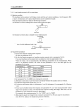
TROUBLESHOOTING
Speed
control
mode
9.1.2
-
No.
1
-
\
Refer
To
Section 9.2
Section 9.2
Section 6.3
Investigation
Possible Cause
Not improved if connectors
cabling is shorted. CNP2 is disconnected.
1.
Power supply of encoder
[mproved when connector
iisconnected.
shorted.
CN1A
and
CNlB
are
Power supply of CN1 cabling is
[mproved when connectors
iisconnected.
2. Servo amplifier is faulty.
C1N14,
CNlB and CNP2 are
1.
Power supply voltage fault
2. Encoder is faulty.
Refer to Section 9.2 and remove cause.
Fault
LED
is
not lit.
LED
flickers.
Start-Up Sequence
'ower on
ilarm occurs.
ilarm occurs.
;ervo motor shaft is
lot servo-locked
is
free).
2 switch on servo-on
,ignal.
e
cause
Refer
to
Section 9.2 and remc
Check the display
to
see if
the servo amplifier is ready
to
operate.
Call the status display and
:heck the input voltage of
the analog speed command.
Call the external I/O signal
display and check the
ON/OFF
status of the input
signal.
Check the internal speed
commands
1
to 3
(parameters No.
8
to
10).
Check the internal torque
limit
1
(parameter No. 28).
Make gain adjustment in the
following procedure:
1.
Increase the auto tuning
response level.
2.
Repeat acceleration and
deceleration several
times
to
complete auto
tuning.
Make gain adjustment in the
following procedure:
If the servo motor may be
run with safety, repeat
acceleration and
deceleration several times
to
complete auto tuning.
1.
Servo on signal is not input.
(Wiring mistake)
2.
24VDC power is not
supplied to COM.
Analog speed command is
OV.
3
hitch on forward
,otation
start
(ST1)
)r reverse rotation
;tart
(ST2).
servo motor does
lot rotate.
Section 6.2
Section 6.6 LSP,
LSN,
ST1 or ST2 is
off
(l),
Section
5.1.2
Set value is
0
Gain adjustment fault
Chapter
7
4
;ain adjustment
iotation ripples
speed 5uctuations)
tre large at low
;peed.
Chapter
7
Arge load inertia
noment causes the
servo motor shaft
to
willate side to side.
Gain adjustment fault
9-
4