
Instruction manual


7.
ADJUSTMENT
A
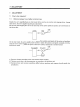
general servo system configuration
is
shown above. The servo control system consists of three loops:
current loop, speed loop and position loop. Among these three loops, the response
of
the inside loop must be
increased
4
to 6 times hgher. If
ths
condtion
is
not satisfied, vibration wlll be generated. If the conhtion
further worsens, hunting
will
occur.
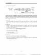
(1)
Current
loop
For
this
servo amphfier, the response level
of
the current loop
is
factory-set
to
a hgh value and need
not be adjusted. If the motor
is
installed
to
the machine, the response
of
the current loop wdl hardly
vary.
(2)
Speed loop
Response wdl vary according to the inertia moment of the machme. When the load inertia moment
increases, the response
of
the speed loop wdl reduce. Use the speed loop gain
(VG2)
to compensate for
the reduction of the response level.
Amplifier gain settig
VG2
[rad/s]
l+m
Speed loop response fv[rad/s]
=
m: Load inertia moment ratio
JL
=
load inertia moment
Jhl=
servo motor shaft inertia moment
(3)
Position
loop
The response level
wdl
not vary according to machne conditions.
Position loop response fp [rads]
=
ampMer gain setting
PG2
[rad/s]
When the motor
is
installed to the machme, the gain must be adjusted
to
satisfy
fv
=
4
to 6fp according
to the load inertia moment ratio m.
7-
2