
Instruction manual


6.
DISPLAY
AND
OPERATION
6.6
External
I/O
signal display
The
ON/OFF
states
of
the dgital
IIO
signals connected to the servo ampuer can be confirmed.
(1
)
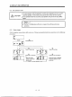
Operation
Call
the display screen shown after power-on.
IC
I
I
0
I
I
0
0
Press
MODE
once.
0
Press
UP
once.
External
I/O signal
display
screen
(2)
Display
definiiion
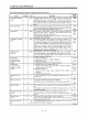
CNl B CNlBCNlB CNlACNlB CNlBCNlB CNlB CNlB
9
07
5
17 15 16
CN1 A CNPP CN10
CNlBCNlB
CNlBCNlA
CNI A
14
9 10
46
19
la
19
Lit: ON
Extinguished:
OFF
The 7-segment LED shown above indxates
ONIOFF.
Each segment at top inhcates the input signal and each segment at
bottom
indxates the output signal.
The signals corresponding
to
the pins in the respective control modes are indicated below:
6-
8