
User`s manual


Table Of Contents
- SAFETY PRECAUTIONS
- CONDITIONS OF USE FOR THE PRODUCT
- REVISIONS
- INTRODUCTION
- CONTENTS
- ABOUT MANUALS
- HOW TO USE THIS MANUAL
- ABOUT THE GENERIC TERMS AND ABBREVIATIONS
- PACKING LIST
- 1. OVERVIEW
- 2. SYSTEM CONFIGURATION
- 3. FUNCTION LIST
- 4. INSTALLATION AND UNINSTALLATION
- 5. SCREEN MAKEUP AND BASIC OPERATIONS
- 6. PROJECT CREATION
- 7. SYSTEM CHECKING FROM PERIPHERAL DEVICE
- 8. DATA SETTING
- 9. WRITING TO/READING OF/VERIFICATION OF POSITIONING MODULE DATA
- 10. POSITIONING DEBUGGING
- 11. USEFUL FUNCTIONS
- APPENDIX
- Appendix 1 Read from Module/Write to Module Reference Processing Times
- Appendix 2 Restrictions Depending on Function Version of QD75
- Appendix 3 Functions Added to/Changed from the Previous Versions
- Appendix 4 Uninstalling the License Key FD
- Appendix 5 Parameter Names Shown in GX Configurator-QP Screens and Manuals
- INDEX
7 - 8 7 - 8
MELSOFT
7. SYSTEM CHECKING FROM PERIPHERAL DEVICE
7.2 System Monitor
PURPOS
E
Check the module configuration, I/O address, Module type and Module axis status
of the station (system) connected.
(Note that this function is not available for LD75/LD77 projects.)
BASIC OPERATIO
N
1. Set the connection target. (Refer to Section 7.1.)
2. Click the [Tool]
[System monitor] menu.
3. The QD75 on the connected station appears in the System monitor dialog box.
4. Click the QD75 illustration and check the I/O address, CPU management,
Module type and Module axis status.
5. To exit, click the "Close" button.
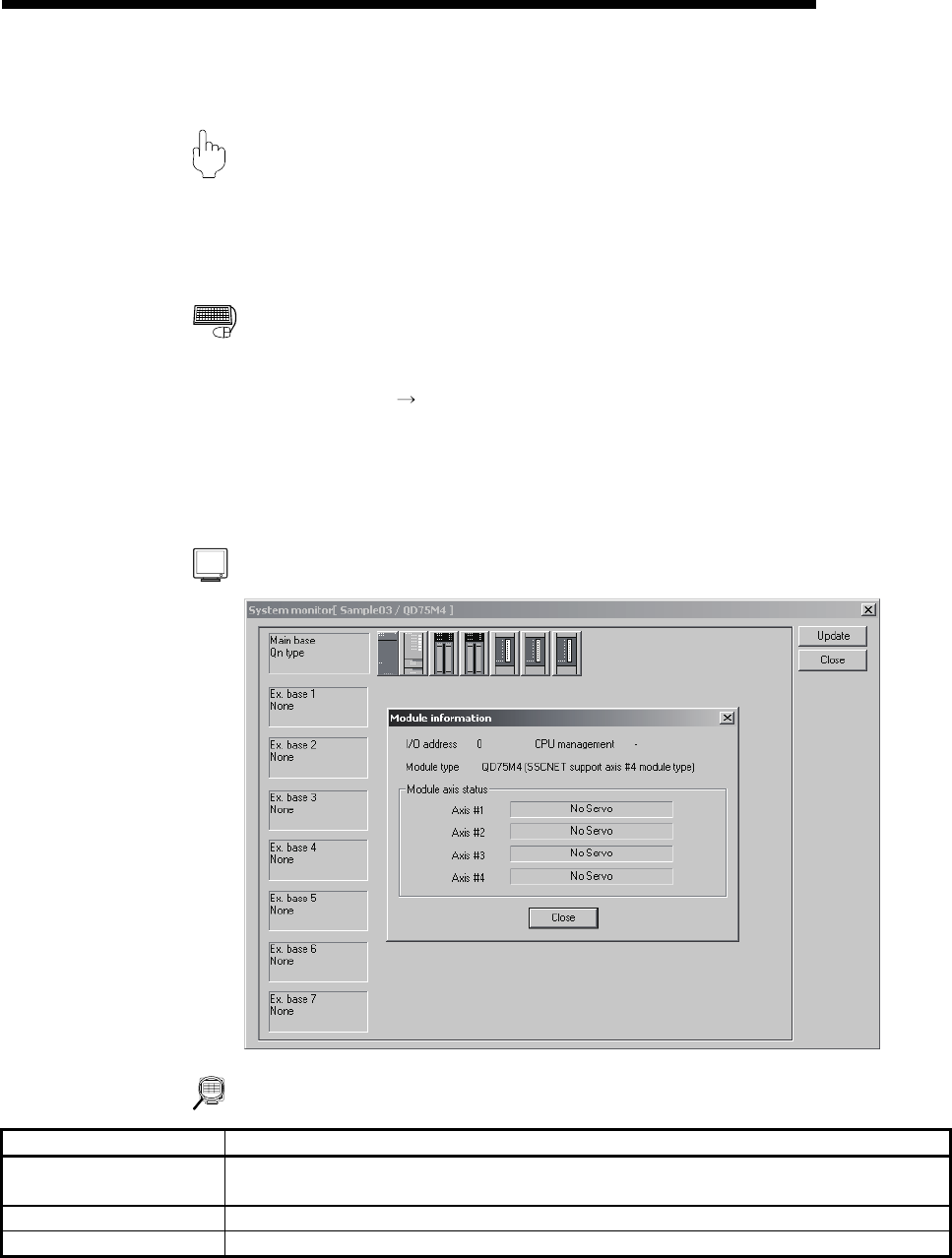
DISPLAY/SETTING SCREE
N
DISPLAY/SETTING DATA
Item Description
System monitor
Shows the connection target programmable controller system.
Clicking the QD75 illustration shows the module information.
Module information Shows the I/O address, CPU management, module type and module axis statuses.
"Update" button Click this button to show the latest system information.