
User`s manual


Table Of Contents
- SAFETY PRECAUTIONS
- CONDITIONS OF USE FOR THE PRODUCT
- REVISIONS
- INTRODUCTION
- CONTENTS
- ABOUT MANUALS
- HOW TO USE THIS MANUAL
- ABOUT THE GENERIC TERMS AND ABBREVIATIONS
- PACKING LIST
- 1. OVERVIEW
- 2. SYSTEM CONFIGURATION
- 3. FUNCTION LIST
- 4. INSTALLATION AND UNINSTALLATION
- 5. SCREEN MAKEUP AND BASIC OPERATIONS
- 6. PROJECT CREATION
- 7. SYSTEM CHECKING FROM PERIPHERAL DEVICE
- 8. DATA SETTING
- 9. WRITING TO/READING OF/VERIFICATION OF POSITIONING MODULE DATA
- 10. POSITIONING DEBUGGING
- 11. USEFUL FUNCTIONS
- APPENDIX
- Appendix 1 Read from Module/Write to Module Reference Processing Times
- Appendix 2 Restrictions Depending on Function Version of QD75
- Appendix 3 Functions Added to/Changed from the Previous Versions
- Appendix 4 Uninstalling the License Key FD
- Appendix 5 Parameter Names Shown in GX Configurator-QP Screens and Manuals
- INDEX
7 - 1 7 - 1
MELSOFT
7. SYSTEM CHECKING FROM PERIPHERAL DEVICE
7. SYSTEM CHECKING FROM PERIPHERAL DEVICE
Specify the QD75/LD75/LD77 to be accessed per project, also check connections with
the external equipment (servo amplifiers, servo motors, etc.), and conduct initial
operation tests of the servo motors.
7.1 Connection Setup
PURPOS
E
Choose an the interface connected to the QCPU, LCPU, serial communication
module, or Q corresponding MELSECNET/H network remote I/O module, and set
the I/O address of the QD75/LD75/LD77 to be accessed.
BASIC OPERATIO
N
1. Click the [Online]
[Connection setup] menu.
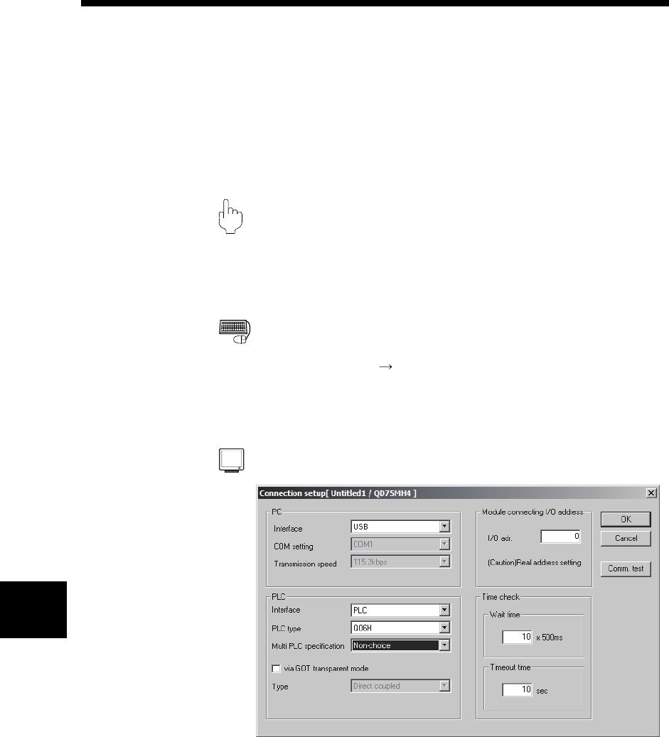
2. Choose the interface in the Connection setup dialog box and set the I/O
address, etc.
3. After the setting is completed, click the "OK" button.
DISPLAY/SETTING SCREE
N
7