
User`s manual


Table Of Contents
- SAFETY PRECAUTIONS
- CONDITIONS OF USE FOR THE PRODUCT
- REVISIONS
- INTRODUCTION
- CONTENTS
- ABOUT MANUALS
- HOW TO USE THIS MANUAL
- ABOUT THE GENERIC TERMS AND ABBREVIATIONS
- PACKING LIST
- 1. OVERVIEW
- 2. SYSTEM CONFIGURATION
- 3. FUNCTION LIST
- 4. INSTALLATION AND UNINSTALLATION
- 5. SCREEN MAKEUP AND BASIC OPERATIONS
- 6. PROJECT CREATION
- 7. SYSTEM CHECKING FROM PERIPHERAL DEVICE
- 8. DATA SETTING
- 9. WRITING TO/READING OF/VERIFICATION OF POSITIONING MODULE DATA
- 10. POSITIONING DEBUGGING
- 11. USEFUL FUNCTIONS
- APPENDIX
- Appendix 1 Read from Module/Write to Module Reference Processing Times
- Appendix 2 Restrictions Depending on Function Version of QD75
- Appendix 3 Functions Added to/Changed from the Previous Versions
- Appendix 4 Uninstalling the License Key FD
- Appendix 5 Parameter Names Shown in GX Configurator-QP Screens and Manuals
- INDEX
11 - 24 11 - 24
MELSOFT
11. USEFUL FUNCTIONS
DISPLAY/SETTING DATA
Item Description
Flash ROM write
Select whether data will be written to flash ROM or not in the initial setting for write to
module.
• YES ......Choose Yes to make the initial setting that data will be written to flash ROM when
write to module is performed.
• NO........Choose No to make the initial setting that data will not be written to flash ROM
when write to module is performed.
Write data enable flag
When you check this check box, any changes in the test mode using positioning data test
edit or teaching are retained after the end of the test mode.
When you do not check this check box, data changes in the test mode are made invalid and
return to the previous data at the end of the test mode.
Positioning data set
Choose the range of the positioning data No. to be displayed on the positioning data edit
window.
• Data No. 1 to No. 100 .....Shows positioning data No. 1 to 100.
• Range..............................Shows positioning data No. 1 to 600.
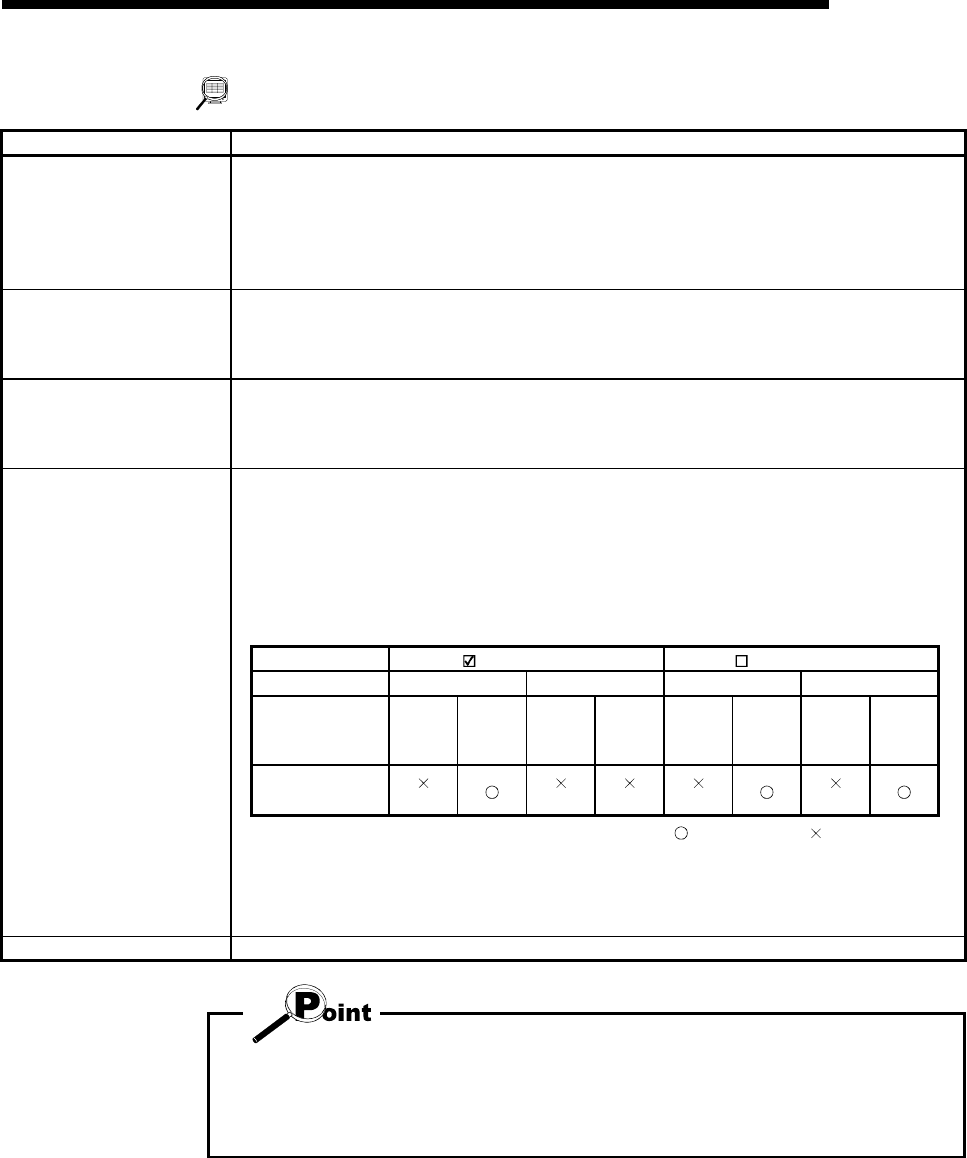
Make selection whether the programmable controller state is checked or not when write to
module, multi module batch write, flash ROM write request or QD75/LD75/LD77 initialization
is executed. (Default is "checked")
Since the set data on the Option screen is saved not on a project basis but on an application
basis, the selected set values apply to all projects.
If you do not choose PLC state check, write cannot be performed when X0
(QD75/LD75/LD77
READY signal) of the corresponding module is ON.
PLC state check PLC state check PLC state check
PLC state STOP except STOP STOP except STOP
X0 status of
corresponding
module
ON OFF ON OFF ON OFF ON OFF
Write processing
(Note 2)
(Note 1)
(Note 1)
(Note 2)
(Note 2)
PLC state check
: Write enabled : Write disabled
Note 1 : "Please make the status of PLC in to STOP or remove the check on the PLC state check on
the option screen. " appears.
Note 2 : "The QD75/LD75/LD77 READY signal is turned on. Please execute again after turning off the
QD75/LD75/LD77 READY signal." appears.
"OK" button Click this button to determine the set data.
When you increased the display range in positioning data display No. setting, it will
take longer until the positioning data edit window appears.
When positioning data No. 101 onwards are not necessary, choose data No. 1 to
No. 100. (The positioning data No. defaults to data No. 1 to No. 100.)