
User`s manual


Table Of Contents
- SAFETY PRECAUTIONS
- CONDITIONS OF USE FOR THE PRODUCT
- REVISIONS
- INTRODUCTION
- CONTENTS
- ABOUT MANUALS
- HOW TO USE THIS MANUAL
- ABOUT THE GENERIC TERMS AND ABBREVIATIONS
- PACKING LIST
- 1. OVERVIEW
- 2. SYSTEM CONFIGURATION
- 3. FUNCTION LIST
- 4. INSTALLATION AND UNINSTALLATION
- 5. SCREEN MAKEUP AND BASIC OPERATIONS
- 6. PROJECT CREATION
- 7. SYSTEM CHECKING FROM PERIPHERAL DEVICE
- 8. DATA SETTING
- 9. WRITING TO/READING OF/VERIFICATION OF POSITIONING MODULE DATA
- 10. POSITIONING DEBUGGING
- 11. USEFUL FUNCTIONS
- APPENDIX
- Appendix 1 Read from Module/Write to Module Reference Processing Times
- Appendix 2 Restrictions Depending on Function Version of QD75
- Appendix 3 Functions Added to/Changed from the Previous Versions
- Appendix 4 Uninstalling the License Key FD
- Appendix 5 Parameter Names Shown in GX Configurator-QP Screens and Manuals
- INDEX
10 - 17 10 - 17
MELSOFT
10. POSITIONING DEBUGGING
DISPLAY/SETTING SCREE
N
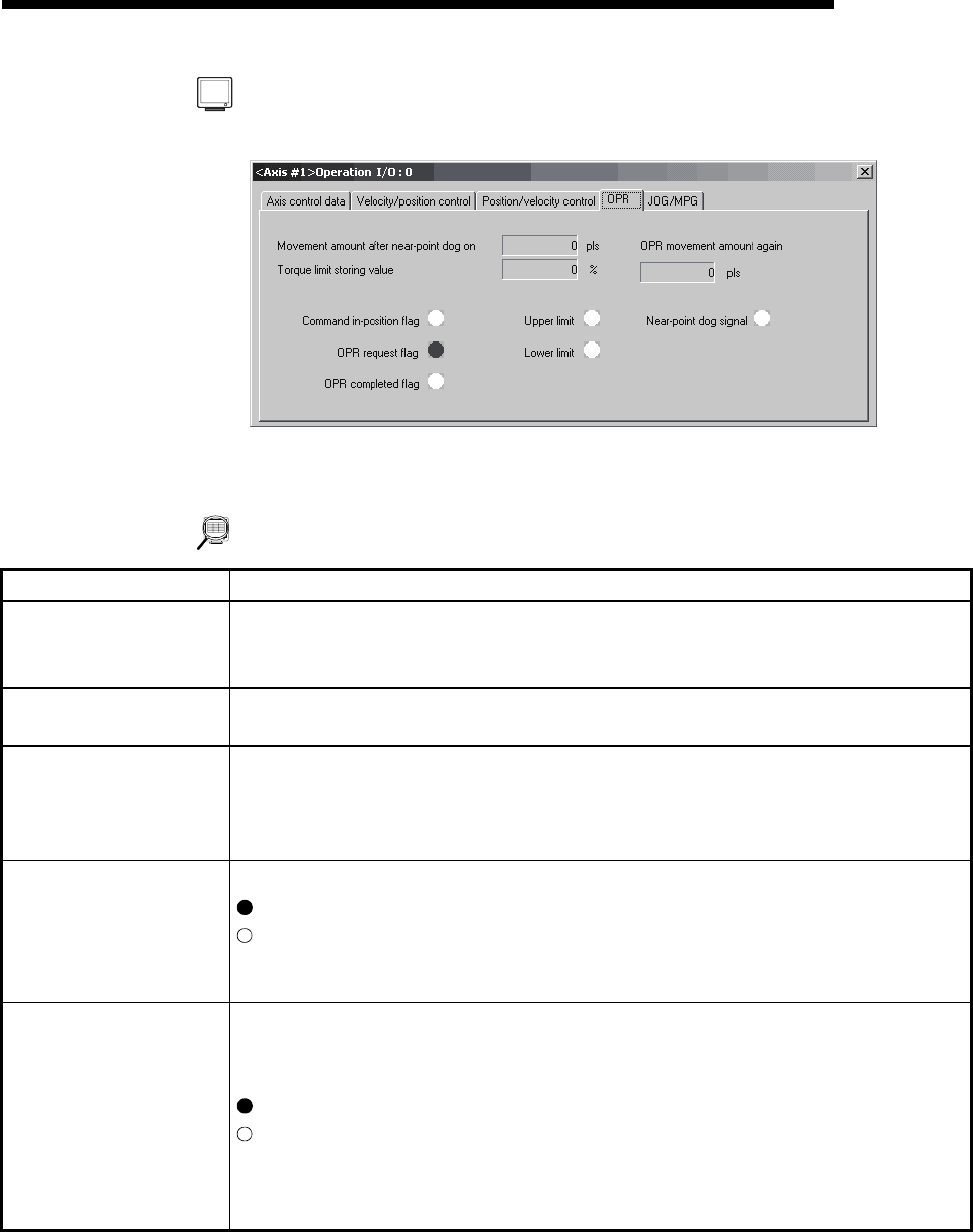
[OPR monitor]
(Screen example: Axis #1 operation monitor screen displayed when the
QD75M is chosen in model selection)
DISPLAY/SETTING DATA
Item Description
Movement amount after
near-point dog On
Indicates the travel distance of the axis during OPR from the position where the limit switch is
turned on by the dog to the position where OPR is completed.
Buffer memory address (Axis #1): 824, 825
Torque limit storing value
Shows the torque limit setting or torque change value.
Buffer memory address (Axis #1): 826
OPR movement amount
again
Indicates the movement amount when the axis is moved to the zero point by re-travel.
This item is displayed only when the QD75M, QD75MH, or LD77 is selected in Select
module type.
Buffer memory address (Axis #1): 848, 849
Command in-position flag
OPR request flag
OPR completed flag
Displays the status signals related to OPR.
: ON
: OFF
Buffer memory address (Axis #1): 817
(b2 : Command in-position flag, b3 : OPR request flag, b4 : OPR completed flag)
Lower limit
Upper limit
Zero phase signal
Zeroing signal
DDC signal
Shows the external I/O signals related to OPR.
(The zero phase signal and DDC signal are displayed when the QD75P,QD75D or LD75 is
selected in model selection.)
: ON
: OFF
Buffer memory address (Axis #1): 816
(b0 : Lower limit, b1 : Upper limit, b5 : Zero phase signal, b6 : Zeroing signal, b8 : DDC
signal)