
User`s manual


Table Of Contents
- SAFETY PRECAUTIONS
- CONDITIONS OF USE FOR THE PRODUCT
- REVISIONS
- INTRODUCTION
- CONTENTS
- ABOUT MANUALS
- HOW TO USE THIS MANUAL
- ABOUT THE GENERIC TERMS AND ABBREVIATIONS
- PACKING LIST
- 1. OVERVIEW
- 2. SYSTEM CONFIGURATION
- 3. FUNCTION LIST
- 4. INSTALLATION AND UNINSTALLATION
- 5. SCREEN MAKEUP AND BASIC OPERATIONS
- 6. PROJECT CREATION
- 7. SYSTEM CHECKING FROM PERIPHERAL DEVICE
- 8. DATA SETTING
- 9. WRITING TO/READING OF/VERIFICATION OF POSITIONING MODULE DATA
- 10. POSITIONING DEBUGGING
- 11. USEFUL FUNCTIONS
- APPENDIX
- Appendix 1 Read from Module/Write to Module Reference Processing Times
- Appendix 2 Restrictions Depending on Function Version of QD75
- Appendix 3 Functions Added to/Changed from the Previous Versions
- Appendix 4 Uninstalling the License Key FD
- Appendix 5 Parameter Names Shown in GX Configurator-QP Screens and Manuals
- INDEX
10 - 15 10 - 15
MELSOFT
10. POSITIONING DEBUGGING
DISPLAY/SETTING SCREE
N
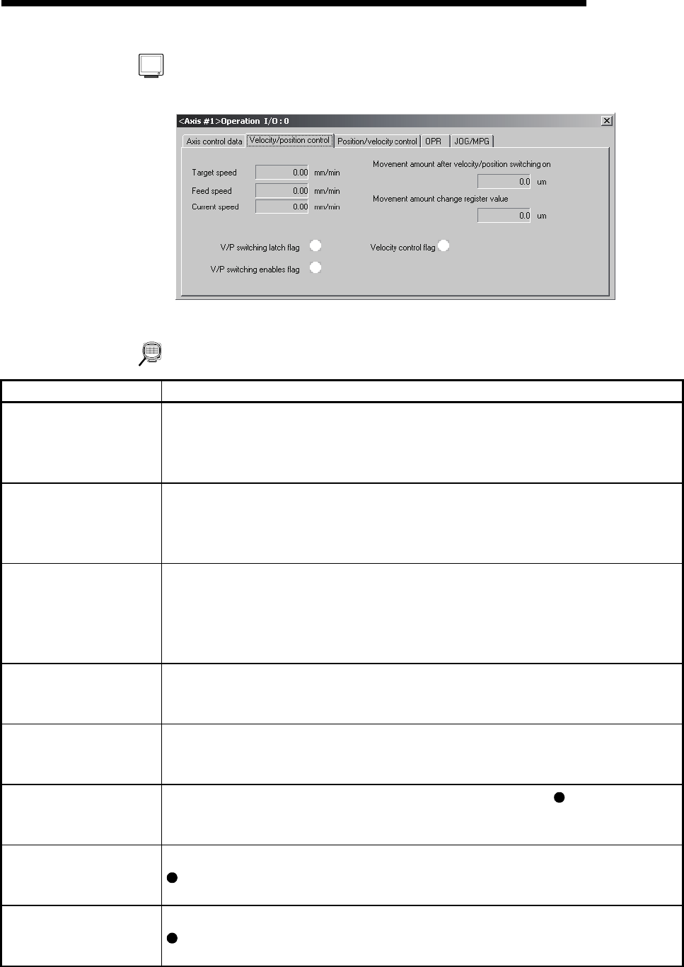
[Velocity/position control monitor]
(Screen example: Axis #1 operation monitor screen)
DISPLAY/SETTING DATA
Item Description
Target speed
Indicates the target speed for positioning data, OPR or JOG operation.
For interpolation control, the composite speed or reference axis speed is displayed for the
reference axis and 0 appears for the interpolation axis.
Buffer memory address (Axis #1): 820, 821
Feed speed
Shows the speed of the axis operating actually in any operation.
For interpolation control, the composite speed or reference axis speed is displayed for the
reference axis and 0 appears for the interpolation axis.
Buffer memory address (Axis #1): 804, 805
Current speed
Indicates the current speed.
For interpolation control, the composite speed or reference axis speed is displayed for the
reference axis and 0 appears for the interpolation axis.
0 appears for JOG operation or MPG operation.
Buffer memory address (Axis #1): 810, 811
Movement amount after
velocity / position switching
ON
Indicates the travel distance under position control when velocity control is changed to
position control during velocity/position switching control.
Buffer memory address (Axis #1): 814, 815
Movement amount change
register value
Indicates the value set to the velocity/position switching control travel correction register in
the program.
Buffer memory address (Axis #1): 1526, 1527
V/P switching latch flag
Indicates the velocity/position switching latch flag for the status signal.
(ON) indicates that
velocity control is switched to position control.
Buffer memory address (Axis #1): 817 (b1)
V/P switching enable flag
Indicates the velocity/position switching enable flag set in the program.
(ON) indicates that switching by the velocity/position switching signal is valid.
Buffer memory address (Axis #1): 1528
Velocity control flag
Indicates the signal for differentiating between velocity control and position control.
(ON) during velocity control.
Buffer memory address (Axis #1): 817(b0)