
User`s manual


Table Of Contents
- SAFETY PRECAUTIONS
- CONDITIONS OF USE FOR THE PRODUCT
- REVISIONS
- INTRODUCTION
- CONTENTS
- ABOUT MANUALS
- HOW TO USE THIS MANUAL
- ABOUT THE GENERIC TERMS AND ABBREVIATIONS
- PACKING LIST
- 1. OVERVIEW
- 2. SYSTEM CONFIGURATION
- 3. FUNCTION LIST
- 4. INSTALLATION AND UNINSTALLATION
- 5. SCREEN MAKEUP AND BASIC OPERATIONS
- 6. PROJECT CREATION
- 7. SYSTEM CHECKING FROM PERIPHERAL DEVICE
- 8. DATA SETTING
- 9. WRITING TO/READING OF/VERIFICATION OF POSITIONING MODULE DATA
- 10. POSITIONING DEBUGGING
- 11. USEFUL FUNCTIONS
- APPENDIX
- Appendix 1 Read from Module/Write to Module Reference Processing Times
- Appendix 2 Restrictions Depending on Function Version of QD75
- Appendix 3 Functions Added to/Changed from the Previous Versions
- Appendix 4 Uninstalling the License Key FD
- Appendix 5 Parameter Names Shown in GX Configurator-QP Screens and Manuals
- INDEX
10 - 13 10 - 13
MELSOFT
10. POSITIONING DEBUGGING
10.2.5 Axis operation monitor
PURPOS
E
Monitor the settings, states and others of the axis control data, velocity/position
control, position/velocity control, original point return and JOG/MPG operation
during operation monitor.
With operation monitor, you can check the detailed states of operation and the
QD75/LD75/LD77 settings made with the program or peripheral device.
For each monitor item, refer to the user’s manual for the positioning module used.
BASIC OPERATIO
N
1. Perform the basic operation in Section 10.2.2 to display the operation monitor
window.
2. Click the "<Axis #1 to #4> Operation" button in the operation monitor window.
3. Click the <<Axis control data>>/<<Velocity/position
control>>/<<Position/velocity control>>/<<OPR>>/<<JOG/MPG>> tab in the
Operation dialog box.
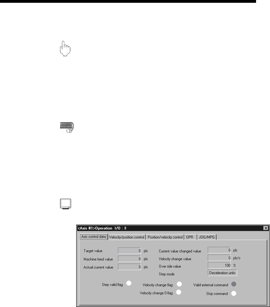
DISPLAY/SETTING SCREE
N
[Axis control data monitor]
(Screen example: Axis #1 operation monitor screen displayed when the QD75M
is chosen in model selection)