
User`s manual


Table Of Contents
- SAFETY PRECAUTIONS
- CONDITIONS OF USE FOR THE PRODUCT
- REVISIONS
- INTRODUCTION
- CONTENTS
- ABOUT MANUALS
- HOW TO USE THIS MANUAL
- ABOUT THE GENERIC TERMS AND ABBREVIATIONS
- PACKING LIST
- 1. OVERVIEW
- 2. SYSTEM CONFIGURATION
- 3. FUNCTION LIST
- 4. INSTALLATION AND UNINSTALLATION
- 5. SCREEN MAKEUP AND BASIC OPERATIONS
- 6. PROJECT CREATION
- 7. SYSTEM CHECKING FROM PERIPHERAL DEVICE
- 8. DATA SETTING
- 9. WRITING TO/READING OF/VERIFICATION OF POSITIONING MODULE DATA
- 10. POSITIONING DEBUGGING
- 11. USEFUL FUNCTIONS
- APPENDIX
- Appendix 1 Read from Module/Write to Module Reference Processing Times
- Appendix 2 Restrictions Depending on Function Version of QD75
- Appendix 3 Functions Added to/Changed from the Previous Versions
- Appendix 4 Uninstalling the License Key FD
- Appendix 5 Parameter Names Shown in GX Configurator-QP Screens and Manuals
- INDEX
10 - 11 10 - 11
MELSOFT
10. POSITIONING DEBUGGING
DISPLAY/SETTING SCREE
N
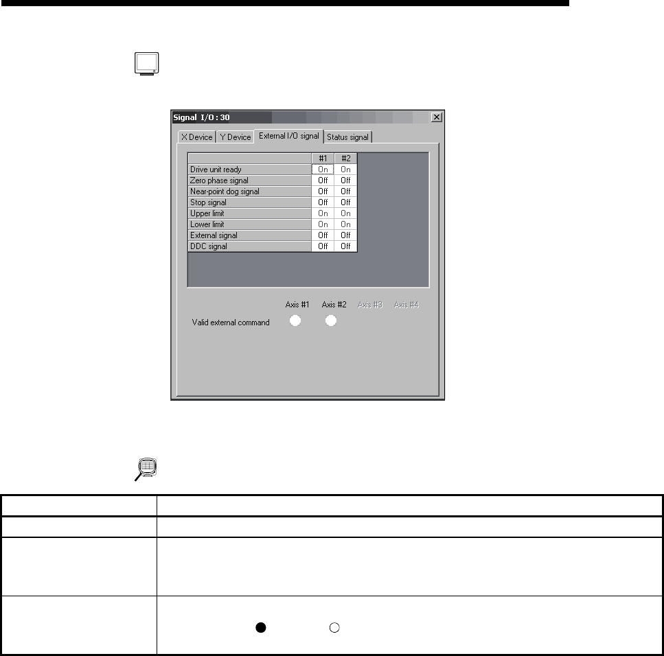
[External I/O signal monitor]
(Screen example: Screen displayed when the
QD75P or QD75D is chosen in model selection)
DISPLAY/SETTING DATA
Item Description
Title bar Shows the I/O address of the QD75/LD75/LD77 being monitored.
External I/O signal
Shows the On/Off states of the QD75/LD75/LD77 's external I/O signals.
The displayed external I/O signal type depends on the model chosen in model selection.
Buffer memory address (Axis #1): 816
Valid external command
Shows whether the start, V/P switch and P/V switch commands given by the external start
signals are valid (
) or invalid ( ).
Buffer memory address (Axis #1): 1505