
User`s manual


Table Of Contents
- SAFETY PRECAUTIONS
- CONDITIONS OF USE FOR THE PRODUCT
- REVISIONS
- INTRODUCTION
- CONTENTS
- ABOUT MANUALS
- HOW TO USE THIS MANUAL
- ABOUT THE GENERIC TERMS AND ABBREVIATIONS
- PACKING LIST
- 1. OVERVIEW
- 2. SYSTEM CONFIGURATION
- 3. FUNCTION LIST
- 4. INSTALLATION AND UNINSTALLATION
- 5. SCREEN MAKEUP AND BASIC OPERATIONS
- 6. PROJECT CREATION
- 7. SYSTEM CHECKING FROM PERIPHERAL DEVICE
- 8. DATA SETTING
- 9. WRITING TO/READING OF/VERIFICATION OF POSITIONING MODULE DATA
- 10. POSITIONING DEBUGGING
- 11. USEFUL FUNCTIONS
- APPENDIX
- Appendix 1 Read from Module/Write to Module Reference Processing Times
- Appendix 2 Restrictions Depending on Function Version of QD75
- Appendix 3 Functions Added to/Changed from the Previous Versions
- Appendix 4 Uninstalling the License Key FD
- Appendix 5 Parameter Names Shown in GX Configurator-QP Screens and Manuals
- INDEX
10 - 8 10 - 8
MELSOFT
10. POSITIONING DEBUGGING
DISPLAY/SETTING SCREE
N
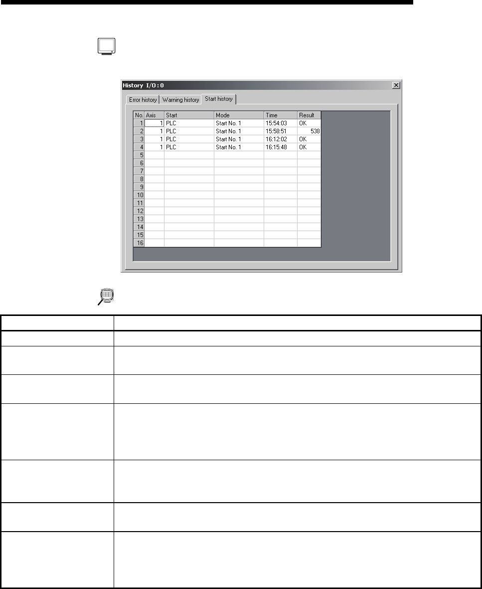
[Start history monitor]
DISPLAY/SETTING DATA
Item Description
Title bar Shows the I/O address of the QD75/LD75/LD77 being monitored.
No
Represents the order of starts since power-on.
If there are more than 16 starts, the older ones are deleted.
Axis
Indicates the axis started.
Buffer memory address: 1212
Start
Indicates the start command destination.
The command destination is the programmable controller CPU, GX Configurator-QP or
external signal.
Buffer memory address: 1212
Mode
Indicates the type of operation started.
The positioning data No. is displayed for operation which uses the positioning data.
Buffer memory address: 1213
Time
Indicates the start occurrence time in hour:minute:second format.
Buffer memory address: 1214, 1215
Result
Shows OK for a normal start.
Shows the error code when an error occurs.
The definition of the error code displayed can be confirmed by the help function.
Buffer memory address: 1216