
User`s manual


Table Of Contents
- SAFETY PRECAUTIONS
- CONDITIONS OF USE FOR THE PRODUCT
- REVISIONS
- INTRODUCTION
- CONTENTS
- ABOUT MANUALS
- HOW TO USE THIS MANUAL
- ABOUT THE GENERIC TERMS AND ABBREVIATIONS
- PACKING LIST
- 1. OVERVIEW
- 2. SYSTEM CONFIGURATION
- 3. FUNCTION LIST
- 4. INSTALLATION AND UNINSTALLATION
- 5. SCREEN MAKEUP AND BASIC OPERATIONS
- 6. PROJECT CREATION
- 7. SYSTEM CHECKING FROM PERIPHERAL DEVICE
- 8. DATA SETTING
- 9. WRITING TO/READING OF/VERIFICATION OF POSITIONING MODULE DATA
- 10. POSITIONING DEBUGGING
- 11. USEFUL FUNCTIONS
- APPENDIX
- Appendix 1 Read from Module/Write to Module Reference Processing Times
- Appendix 2 Restrictions Depending on Function Version of QD75
- Appendix 3 Functions Added to/Changed from the Previous Versions
- Appendix 4 Uninstalling the License Key FD
- Appendix 5 Parameter Names Shown in GX Configurator-QP Screens and Manuals
- INDEX
9 - 4 9 - 4
MELSOFT
9. WRITING TO/READING OF/VERIFICATION OF POSITIONING
MODULE DATA
<Verify module data>
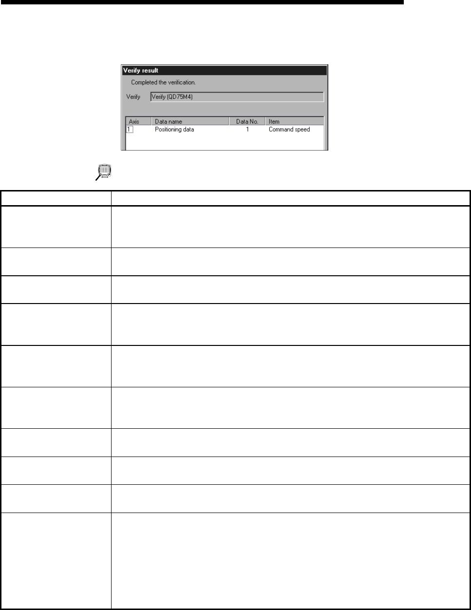
[Verify result dialog box]
DISPLAY/SETTING DATA
Item Description
Positioning data
Block start data
Parameter
Set the data used for write to QD75/LD75/LD77/read from QD75/LD75/LD77/verify
QD75/LD75/LD77 data from positioning data, block start data and parameters.
Block start data includes condition data.
"Flash ROM write" check
box
When performing write to QD75/LD75/LD77, set a request to write from buffer memory to
flash ROM at the same time.
Current type
Set the model of the QD75/LD75/LD77 connected to the peripheral device and the range of
write/read/verify.
<<Positioning data>> tab
<<Block start data>> tab
<<Parameter data>> tab
Click the corresponding tab to display the screen which is used to set the axes and ranges of
the data for write to QD75/LD75/LD77/read from QD75/LD75/LD77/verify QD75/LD75/LD77
data.
<<Positioning data>> tab
screen
Set the axes of the positioning data used for write to QD75/LD75/LD77/read from
QD75/LD75/LD77/verify QD75/LD75/LD77 data.
Also, set the positioning data No.s in the write/read/verify range on an axis by axis basis.
<<Block start data>> tab
screen
Set the axes of the block start data used for write to QD75/LD75/LD77/read from
QD75/LD75/LD77/verify QD75/LD75/LD77 data.
Also, set the range of the QD75/LD75/LD77 write/read/verify block on an axis basis.
<<Parameter data>> tab
screen
Set the axes used for write to QD75/LD75/LD77/read from QD75/LD75/LD77/verify
QD75/LD75/LD77 data.
<<Servo parameter data>>
tab screen
Set the axes used for write to QD75/LD75/LD77/read from QD75/LD75/LD77/verify
QD75/LD75/LD77 data
"OK" button
Click this button to start write to QD75/LD75/LD77/read from QD75/LD75/LD77/verify
QD75/LD75/LD77 data.
Verify result dialog box
After QD75/LD75/LD77 data verify is completed, differences between the QD75/LD75/LD77
and project appear.
The screen displays that the speed limit value of the axis #1 basic parameter 2 and the
software stroke limit upper/lower limit value of the extended parameter 1 differ between the
QD75/LD75/LD77 and project.
If there are more than 100 mismatches, verify processing is suspended as soon as the
number of mismatches reaches 100.