
User`s manual


Table Of Contents
- SAFETY PRECAUTIONS
- CONDITIONS OF USE FOR THE PRODUCT
- REVISIONS
- INTRODUCTION
- CONTENTS
- ABOUT MANUALS
- HOW TO USE THIS MANUAL
- ABOUT THE GENERIC TERMS AND ABBREVIATIONS
- PACKING LIST
- 1. OVERVIEW
- 2. SYSTEM CONFIGURATION
- 3. FUNCTION LIST
- 4. INSTALLATION AND UNINSTALLATION
- 5. SCREEN MAKEUP AND BASIC OPERATIONS
- 6. PROJECT CREATION
- 7. SYSTEM CHECKING FROM PERIPHERAL DEVICE
- 8. DATA SETTING
- 9. WRITING TO/READING OF/VERIFICATION OF POSITIONING MODULE DATA
- 10. POSITIONING DEBUGGING
- 11. USEFUL FUNCTIONS
- APPENDIX
- Appendix 1 Read from Module/Write to Module Reference Processing Times
- Appendix 2 Restrictions Depending on Function Version of QD75
- Appendix 3 Functions Added to/Changed from the Previous Versions
- Appendix 4 Uninstalling the License Key FD
- Appendix 5 Parameter Names Shown in GX Configurator-QP Screens and Manuals
- INDEX
8 - 13 8 - 13
MELSOFT
8. DATA SETTING
8.4 Simulation
PURPOS
E
Execute simulation (virtual positioning) with the set positioning data to check the
operation of the axis.
The axis speed is displayed as waveform data for 1-axis control or as locus data
for 2-axis interpolation control.
You cannot perform simulation for 3-/4-axis interpolation control.
BASIC OPERATIO
N
1. Open the positioning data edit window.
Double-click.Double-click.
2. Click the [Edit]
[Simulation] menu.
3. Type the Positioning Start No. of positioning data in the simulation window.
4. Setting or changing the positioning data being simulated in the positioning data
edit window shows the simulation result at the point of data input.
5. To exit, click the "Close" button.
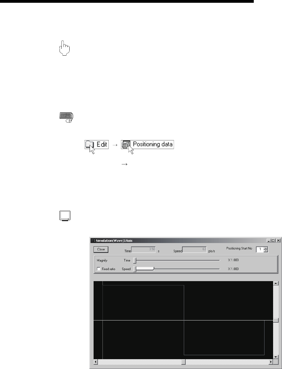
DISPLAY/SETTING SCREE
N
[Waveform data for 1-axis control]