
Specifications


137
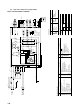
(c) Ceiling recessed single are supply port type (FDTQ)
Models FDTQJ22HKXE3, 28HKXE3, 36HKXE3
Function of switches
Mark Function
SW5-1 ON
OFF
ON
OFF
ON
OFF
Reverse Invalid
Run Stop
Input
signal
SW5-2
Mark Color
BK
BL
BR
GR
OR
Black
Blue
Brown
Gray
Orange
Mark Color
RD
WH
Y
Y/GN
Red
White
Yellow
Yellow/Green
Color mark
Note (1) 1.Sections marked by 1 (LM and LS) are not equipped on the duct panel.
Heating temp. shift + 3
Normal
Test run of condensate pump motor
Normal
SW5-3
Meaning of marks
Mark Parts name Mark Parts name Mark Parts name
FM
I
49F
I
CF
I
DM
FS
LM
LS
SM
X1,2,3
X4
X5
Thc
Fan motor
Internal thermostat for FM
I
Capacitor for FM
I
Drain motor
Float switch (For overflow prevention)
Louver motor
Limit switch
Stepping motor (For Exp.v)
Auxiliary relay (For FM
I
)
Auxiliary relay (For DM)
Auxiliary relay (For LM)
Thermistor
ThI-A
ThI-R
SW1
SW2
SW3
SW4
SW6
Trl
Val
LED
·
R
LED
·
G
F
Thermistor
Thermistor
Indoor unit address ten's place
Indoor unit address unit's place
Outdoor unit address ten's place
Outdoor unit address unit's place
Change of heat pume type
Transformer
Varistor
Indication lamp (Red)
Indication lamp (Green)
Fuse
CnA-Z
TB
mark
mark
XR1
XR2
XR3
XR4
XR5
SK
Connector ( mark)
Terminal block
Terminal (F)
Connector
Operation indication (DC12)
Heating indication (DC12)
ON indication for CM (DC12)
Check indication (DC12)
Distant operation
Spark killer
Tap change of fan equipment
Standard tap (at shipping)
High speed tap (for ducted type)
RD
BK
BR
WH
RD
BK
WH
WH
CnF
1
Motor
side
Control
box side
6 pole flat
connector
WH
CnF
1
BK
BR
WH
RD
RD
CnF
2
Chenge connectors located at the inside of control box due
to the follwing procedure in case of using for ducted type.
Motor
side
Control
box side
RD
BK
BR
WH
BK
BR
WH
WH
CnF
1
RD
CnF
2
RD
BK
WH
RD
WH
CnF
1
CnK2
CnK
TB
B
A
TB
CnU
N
L
RD
RD
RD RD
RD
RD
RD
RD
BL
RD
RD
RD
Y/GN
Y/GN
Y/GN
BL
BL
BK
BL
BK
BK
BK
BK
RD
RD
WH
WH
BK
BK
BK
BK
OR
RD
Y
BK
GR
OR
RD
Y
BK
GR
BL
BK
BK
GR BR OR
OR
OR
1
BR
BR
BK
WH WH
WH
BL
BL
Power
source
Outdoor
unit
(Signal line)
F(3.15A)
2
1
CnO
X4
X3
X2 X5
X1
X3
X2
X1
6
78
SK
CnR CnJ
CnJ
CnR
DM LM
CnI
CnI
FS
CnF
2
CnF
1
CnF
2
CnF
1
X4 X5
CFI
VaI
9
43
CnD
(49FI)
5
UH
Y
OR
WH
WH
WH
WH
WH
WH
WH
WH
WH
WH
WH
WH
H
L
FM
I
SM
TrI
8V
17V
CnN
CnS
CnT
CnA
CnH
CnW1
CnB
Remote
controller
Printed circuit board
CnW2
SW4SW3
SW1
Checker
CheckNormal
SW2
LED·G LED·R
HACnZ
CnE
SW6
SW5
220/240V
OFF
ON
OFF
ON
43
21
3
21
J5 J6 J7
J1 J2 J4J3
XR4
XR3
XR2
XR5
XR1
CnA2
ThI-R
1
ThI-A
CnN2
BL
BL BK
BK
LS
CnS2
TB
Z
Z
Y
Y
X
X
Thc
Option