
Specifications


111
ø15.88
(5/8")
SVC
SVH
SVL
SVG
SVC
SVH
SVL
Liquid
piping
ø12.7
(1/2")
Discharge gas
piping
ø19.05
(3/4")
Service
valve
(with charge
port)
Check
joint
Flange
DPR
2
DPR1
20SS 20SL
SVS SVL
DPR
3
20
VF
20
VU
DD
63L
SV
3
SV2
SV1
63H2
63H4
63H3
63H1
E
SC
(LP)
Intake gas piping
224 : ø25.4
280 : ø28.58
4-way valve
(For before heat exchange)
4-way valve
(For after heat exchange)
Brazing
Brazing
Flare connection
Sub-cooling coil
(Discharge)
Oil separator
Accumu-
lator
(Release)
Service
valve
Full
load
Partial
load
Capacity control solenoid valve
Check joint
(liquid)
Check joint
(HP)
Outside tempera-
ture thermistor
(Th
O-A)
Heat ex-
change
ther-
mistor
(Th
O-R)
Discharge
piping
thermistor
(Th
O-D)
Service valve
(With charge port)
Compressor
Receiver
(with charge
port)
Flare connection
Dome bottom thermistor
(Tho-c)
Brazing
SVG
( )
( )
(Suction)
Fusible plug
Strainer
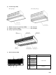
2.2.5 Piping system
Models FDCP224HKXRE2A, 280HKXRE2A
FDCP224HKXRE2V, 280HKXRE2V
(3) Function of thermistor
Th
O-A
: For low outside air cooling/heating, frost removal control
Th
O-R
: For frost removal control
Th
O-D
: For Discharge piping temperature control
Th
O-C
: For dome bottom temperature control
Th
I-R
: For fan control during heating
For frost prevention during cooling
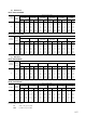
(4) Flow divide controller solenoid valve action chart
SVH
SVC
Closed
Closed
Power
supply
OFF
Closed
Open
Power
supply
ON
Closed
Open
Cool-
ing
(1)
Open
Closed
Heat-
ing
(1)
Closed
Open
Blower
Closed
Open
Detrost
Note (1) Including for pauses, stops, and errors.
(2) Preset point of protective devices
63H
1
: 3.24 open, 2.65 closed MPa [for protective]
63H
2
: 2.26 open, 2.84 closed MPa [for high-pressure control (Hz decrease)]
63H
3
: 2.50 open, 2.11 closed MPa [for high-pressure decrease control]
63H
4
: 1.67 open, 1.86 closed MPa [for high-pressure increase control]
63L : 1.96 open, 2.75 closed MPa [for low-pressure increase control]
DPR
1,2
: 1.77 open MPa DPR
3
: 2.35 open MPa
(1) Solenoid valve operation chart
SV1
20VF
20VU
Full load
During compressor capacity control
Partial load
-
Open
Closed
-
Closed
Open
Open
-
-
During
discharge
temperature and
dome bottom
temperature
control
Note (1) The solenoid valve is open during magnetic induc-
tance and closed when there is not magnetic induc-
tance.
Indoor unit A
Indoor unit B
Flow divide controller
Outdoor unit Refrigerant flow Cooling Heating
To the units in the following
order. (A maximum or 12
(224), 16 (280) units can be
connected.)