
Specifications


105
30
105
( 900)
150
250
400
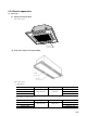
¡Inspection Ports
Inspection Port
Service Space
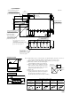
(iii) HPFDO6R-E
Note (1) If the number of indoor connected units is less than the number of branches, connect in se-
quence from the front right side. Tighten securely the flare connectors not in use.
(2) Always attach an accessory strainer at the outdoor discharge gas connection port.
(3) Flow divide controllers cannot be installed upside
down. Install them so that the indoor unit is level.
(4) If space of 400 or more is available above the flow
divide controller (* mark), inspection ports can be
located at the points shown in the figure right.
(Change the position of the relay box.)
(5) Weight: 35kg
(6) Connect an appropriate different diameter adapter
coupling selected from the table below depending on
the capacity of the indoor unit to be connected.
(Use the flare nut attached to the flow divide controller.)
Quantity equal
to the number
of branches
Quantity equal
to the number
of branches
Different diameter adapter coupling
For indoor
gas piping
For indoor
liquid piping
For outdoor intake
gas piping
For outdoor dischage
gas piping
For outdoor
liquid piping
1 unit 1 unit 1 unit
OD15.88
ID12.7
ID19.05
OD25.4 OD19.05 OD12.7
ID19.05 ID15.88
ID9.52
OD9.52
ID6.35
ABCDE
( 450)
Inspection Ports
Relay box
Unit: mm
150
770
21
48
25
25
319
109 79 79 86105
372
67.5
32.5
40
110
40
110
722298
62 80
No. 1 No. 2 No. 3 No. 4 No. 5 No. 6
270
65
Outdoor refrigerant piping connection
port (intake gas)
φ
28.58 brazing
(Suspension bolt attachment pitch)
Relay box
Suspension bolt position
M10 × 4 bolts
(
Parts prepared locally
)
Accessory intake gas piping
(with flange)
Accessory discharge gas piping
(with strainer)
Outdoor refrigerant piping connection
port (discharge gas)
φ
19.05 brazing
Outdoor refrigerant piping con-
nection port (liquid)
φ
12.7 flare
(Upon attachment of accessory piping)
Indoor connection wiring (length 200)
(with butt terminal)
Indoor refrigerant piping connection port
(gas)
φ
15.88 flare
Indoor refrigerant piping connection
port (liquid)
φ
9.52 flare
At
φ
15.88 connection, use accessory dif-
ferent-diameter coupling D
(
)
Cut when using
φ
25.4; at
φ
15.88 connection,
use accessory different-diameter coupling C
(
)
At
φ
9.52 connection, use accessory
different-diameter coupling E
(
)
At
φ
19.05 or
φ
12.7 connection, cut and use
accessory different-diameter coupling A.
(
)
At
φ
6.35 connection, use accessory
different-diameter coupling B
(
)
196
Upon attachment
of accessory piping
(
)