
Specifications


69
Item
W
W
kg
kW
RS5555HAV31 RS5570HAV31
340
dB(A)
%
W
kg
W
CMM 175
mm(in)
mm
Models
FDCP280HKXRE2V
(3)
28000
FDCP224HKXRE2V
(3)
22400
25000
3 Phase 380V 50HZ
Direct start
Direct start
Brazing
Discharge gas side connection piping (for service valve and back direction connections),
intake gas side connection piping (for service valve and back direction connections)
FDTJ28, 36, 45, 56, 71, 90, 112, 140
FDTWJ28, 45, 56, 71, 90, 112, 140
FDTQJ22, 28, 36
FDTSJ45, 71
FDRJ45, 56, 71, 90, 112, 140
FDQMJ36
FDUMJ36, 45, 56, 71, 90, 112, 140
FDEJ36, 45, 56, 71, 112, 140
FDKJ22, 28, 36, 45, 56, 71
FDFLJ28, 45, 71
FDFUJ28, 45, 56, 71
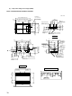
Hole for drain( 20 6pcs)
Necessary (both Liquid &Gas lines)
60
31500
Models FDCP224HKXRE2V, 280HKXRE2V
361
3.7 (MA32) 3.7 (MA32)
11
100 ~ 22.0
40
5.5
R407C
7.5
1700 1350 600
Nominal cooling capacity*
1
Power source
Nominal heating capacity*
2
Net weight
Capacity control
Crankcase heater
Heat exchanger
Refrigerant control
Refrigerant
Quantity
Refrigerant oil
Defrost control
Starting method
Exterior dimensions
Height Width Depth
Refrigerant equipment
compressor type & Q' ty
Noise level
Motor
(1) The cooling and heating capabilities imply the values when the indoor unit of rated capacity is connected under the condition specified in ISO-TI.
Flow divide controller part No. list
(2) The refrigerant quantity in the connecting pipe is not included Charge it additionally at the site.
(4) When an individual flow divide controller is used a pipe part set is required.
Notes
(3) The number "2", following the type of each model, represents"CE-marked model" especially for European Union, and for European nations which
require CE marking.
Type
Central flow
divide controller
Individual flow divide controller
For 2 units (2 divisions)
For 4 units (4 divisions)
For 6 units (6 divisions)
HPFD01R-E
HPFD02R-E
HPFD04R-E
HPFD06R-E
FDCP224,280
Part No.
Type
Horizontal division (for 3 pipes)
Division [For 2 pipes (Used at the same mode of cooling/heating)]
Vertical division (for 3 pipes)
DIS-1KXR2-E
DIS-1KXR3-E
DIS-V1KXR3-E
FDCP224,280
Part No.
Air handling equipment
Fan type & Q'ty
Motor
Starting method
Air flow(Standard)
Shock & vibration absorber Rubber mount (for compressor)
Compressor overheat protection, overeurrent protection, power transformer overheating
protection, abnormal high pressure protection
Safety equipment
Connecting method
Drain
Insulation for piping
Accessories
Indoor units to be combined
Installation data
Refrigerant piping size
Expansion Valve +Capillary tube
MC controlled De-Icer
Louver fines & inner grooved tubing
Propeller fan 2
100 2
Liquid line: 12.7(1/2")
Intake gas line: 25.4(1")
Discharge gas line: 19.05(3/4")
Liquid line: 12.7(1/2")
Intake gas line: 28.58(11/8")
Discharge gas line: 19.05(3/4")