
Specifications


279
TB Tr
L1
L2
L3
N
52C
CNA1
CNA2
Noise filter
LED1 LED2 LED3~5
Red Green
Control Circuit board
Transformer
~
~
~
+
1
2
3
4
5
6
7
1
2
3
4
5
6
7
Cn1
Cn1
Cn5
CT
R1
Cn2
Cn13
Cn14
Cn7
Cn8
Cn9
Cn10
Cn11
Cn12
Resistance
module
LD1 LD2 LD3 LD4
Green Red Red Red
Inverter circuit board
1234
+
+
1 2 3 6 7 10 11 14 15 1 2 3 4 5 6 9 12 14
Cn3
23F
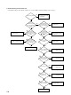
Outdoor Unit Check Points
Check the part marked * while the power supply is turned ON.
Make checks after the power supply is turned OFF,
or after removing each part.
Power cable check: To see if there is continuity and
connections are correct.
Noise filter check: There should be continuity.
Fuse check: There should be continuity.
7
Power check:
Measure the power at the L
1
, L
2
, L
3
and N on the terminal block TB.
*
Diode module check
When the tester bars are re-
versed, the resistance value is
about 10 ~ 20 Ω
Transformer check: Disconnect the
connector CNA1. There should be
continuity on the primary side.
6
5
+
~+
~
When the
result is OK
Tester bar
8
4
Reactor continuity check:
After disconnecting the connector and make a continuity
check. At that time, there should be continuity.
FDCP224, 280 6.8 Ω
*
Normality LED2 check: If this
LED flashing, the operation of
the microcomputer is normal.
Communication checked at CNI will show the following values.
Cn1
1
2
3
4
5
6
7
Contents of communication
Common
12 V power supply
Transmission from inverter
Reception from inverter
Watch dog (communication from the inverter
circuit board to the outdoor unit PCB)
Inverter overheating
Current cut
V (analog tester)
0V
12V
Swings between 11V and 11.5V.
Swings between 4.5V and 5V.
Swings between 2V and 4V.
5V: normal, 0V: abnormal
5V: normal, 0V: abnormal
Connector
Check the appeaeance for damage
and blister and check the charging
characteristic with a tester.
(The indicator swings and returns
slowly. After changing the polarity,
perform the same operation. If the
indicator returns, this is regarded as
normal.)
Power transistor output check:
Disconnect the Faston terminal of the compressor and measure the output voltage.
(The output 2001 is for the case whese the inverter is not loaded.)
Unit: V (AC)
FDC 224, 280 type
35Hz
95~98
40Hz
104~107
65Hz
167~173
75Hz
180~190
80Hz
195~197
95Hz
198~203
Frequency
Modells
Check the appearance for crack or damage.
2
3
Mark
Tester bar
(red)
Tester bar
(black)
Power transistor module
CM
U
V
W
Inverter PCB output check:
Disconnect the connector and mea-
sure the signal output to the power
transistor module.
(+)
Cn13- 6
Cn13-10
Cn13-14
Cn14- 4
Cn14- 5
Cn14- 6
(-)
Cn13- 7
Cn13-11
Cn13-15
Cn14- 1
Cn14- 2
Cn14- 3
Voltage
DC 1.5 ~
1.6V
Tester bars
1
*
*
LD1 check:
When this LED flashing every 0.5 second,
it is normal.
LD2: Power transistor overheating
LD3: Current cut
LD4: Serial transmission error
On the above occasion, these LDs light up.
DC280V
Capacitor check:
Resistor R1 inspection