
Specifications


228
90 56Indoor unit 22
Central flow divide controller 1
Central flow divide
controller 2
22 22 22
90 22
a
C
A
B
bc
d
e
f
gh
FDCP
280HKXRE2A
Outdoor unit
Branch piping 1
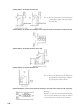
Example of piping
Central flow divide controller system
Total capacity : 346
Floor
Floor
Good
Good
No No
Floor
Floor
Horizontally
Vertically
Note (1) When making branch connections (for both gas and liquid lines), be sure that the proper horizontal branches
and vertical branches are used.
A
B
C
a
b
c ~ f
g
h
Item Selection procedure
Discharge gas line
φ
19.05
φ
15.88
φ
19.05
Intake gas line
φ
28.58
φ
19.05
φ
25.40
Piping size (mm)
Liquid line
φ
12.7
φ
9.52
φ
12.7
φ
9.52
φ 9.52
φ 6.35
φ 9.52
φ 6.35
φ
15.88
φ
15.88
φ 12.70
φ 15.88
φ 12.70
Same as the outdoor unit piping size (FDCP280HKXRE2A)
Total capacity of the connected indoor unit (90+22) 112
Total capacity of the connected indoor unit (90+56+22+22+22+22) 234
Indoor unit piping size (90)
Indoor unit piping size (56)
Indoor unit piping size (22)
Indoor unit piping size (90)
Indoor unit piping size (22)
● Selecting piping size
●
Selection of central flow divide controller
●
Branch piping set
Item
Central flow divide controller 1
Central flow divide controller 2
Selection procedure
Central flow divide controller
HPFD06R-E
HPFD02R-E
Item
Branch piping 1
Select according to the number
of indoor units to be connected.
Branch piping set
DIS-1KXR3-E
Note (1) Select the appropriate different diameter adapter coupling attached to the central flow divide controller according to the pipe size.
Usable central flow divide controller in more than 8 indoor units connecting.
9, 10 units
11, 12 units
13, 14 units
15, 16 units
HPFD04R-E + HPFD06R-E
HPFD06R-E × 2 or HPFD04R-E × 3
HPFD04R-E × 2 + HPFD06R-E × 1
HPFD04R-E + HPFD06R-E × 2 or HPFD04R-E × 4
Central flow divide controller
Number of connected indoor units