
Specifications


226
Notes(1) Each flow divider pipe is
surrounded with insula-
tion.
(2) Each pipe is cut off in the
middle of the diameter that
is used in that locality.
Branch pipe set part shapes
(DIS-1KXR3-E)
Symbol Name
Branch pipe
Reducer
Part shape Quantity
1
Remarks
Intake gas piping
1 Discharge gas piping
1 Liquid piping
1
Intake gas piping
[
FDCP280HKXRE2A
(
V
)]
1
2
3
a
15.88
19.05
19.05
19.05
15.88
12.7
15.88
424
247
100
12.7
12.7
12.7
9.52
12.7
9.52
6.35
94.5
128
ID
ID
25.4
OD
28.58
ID
19.05
25.4
15.88
15.88
19.05
19.05
15.88
519
25.4
12.7
12.7
119
ID
25.4
Notes (1) Insulation is provided to
all flow divider pipes.
(2) Cut off the flow divider
pipes in the center to
match the diameter of the
piping used on site.
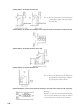
Shapes of accessory parts for brunch pipe set for vertical divides (DIS-V1KXR3-E)
1
2
3
Classifi-
cation
Intake gas piping
Intake gas piping
Discharge
gas piping
Liquid piping
Symbol
Branch pipe
—
—
Classifi-
cation
Symbol
Reducer
Reference 1: Be sure to install the vertical flow divider coupling
(both) for gas and liquid) as "vertical divide" as
illustrated below.
100
ID28.58
OD25.4
100
ID
φ25.4
OD
19.05
Floor
15.88
285
ID
ID
ID
120
12.7
19.05
15.88
12.7
130 98
19.05
25.4
19.05
15.88
12.7
19.05
19.05
15.88
15.88
12.7
19.05
15.88
424
247
94.5
12.7
9.52
12.7
12.7
9.52
6.35
128
Liquid piping
Flow divider
pipe set for ver-
tical divides
(DIS-V1KXR3-E)
Discharge gas piping
Intake gas piping
Individual flow
divide controller
Individual flow
divide controller
Indoor unit
Outdoor unit
Indoor unit
(Example)
When the outdoor unit are installed at a higher level than the individual flow divide controller and a
vertical flow divider is required for the piping connections of 2 or more individual flow divide controllers
for 1 module, use the "flow divider pipe set" for vertical divides.
●Flow divider pipe set for vertical divides Part No. DIS-V1KXR3-E