
Specifications


218
(e) Set necessary functions in accordance with the model of in-
door unit.
(f ) Couple the upper case with the lower case as they were.
(g) Secure the remote controller cords on the wall or other using
cord clamps.
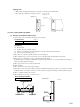
Embedded installation
1)
Have a electrical box and remote controller cords (use shielding wires or
twisted pair wires for extension) embedded in the wall in advance.
2) Remove the upper case from the remote controller.
3) Secure the remote controller body on the electrical box with 2 pieces
of M4 round head screw (provided by customer).
4) Connect remote controller cords with the remote controller.
(Refer to the section regarding the exposed installation.)
5) Couple the upper case with the lower case as it was to finish up the
installation.
Cautions for extension of remote controller cords
● Make sure to use shielding wires only.
• All models: 0.3 mm
2
x 3 core wires [MVVS3C, products of
Keihan Cables]
Note (1) When the extension distance exceeds 100 m, change the wire size as
follows:
100 ~ 200 m ... 0.50 mm
2
3 core wires
~ 300 m ... 0.75 mm
2
3 core wires
~ 400 m ... 1.25 mm
2
3 core wires
~ 600 m ... 2.00 mm
2
3 core wires
●
Make sure to ground one side only of the shielding wire.
Switch Function
SW1
C Model type - Cooling only
H Model type - Heat pump model
SW2
ON Remote control sensor - Valid
OFF Remote control sensor - Invalid
SW3
ON
Power failure compensation - Provided
OFF
Power failure compensation - Not provided
SW4
S Remote controller selector - Slave
M
Remote controller selector - Master
Name Function
J1
With
Return air temperature display - Valid
None
(1)
Return
air temperature display - Invalid
J2
With Blow rate display - 3 speed
None
(1)
Blow rate display - 2 speed
J3
With Timer function - Valid (Normal)
None
(1)
Timer function - Invalid
J4
With Auto swing display-With
None
(1)
Auto swing display - None
J6
With For KX multi
None
(1)
For KXR multi
Electrical box
(Provided by customer)
Remote controller cords
M4 round head screw x 2 pieces
(Provided by customer)
Upper case
Heat sensor
element
Selector switch
(SW1 ~ SW4)
Jumper wire
(J1 ~ J4)
J6
(3) Setting the functions
Change the setting of selector switches (WS1 SW4)
and jumper wires (J1 J6) in accordance the func-
tions of indoor unit and purposes of use.
To indoor unit
~
~
Functions of selector switches
Functions of jumper wires
Note (1) “None” means it is not installed on the PCB or open.