
Specifications


215
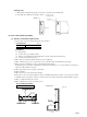
4) Wiring route.
a) Wire from the wiring hole through the rear side of the control box to the terminal block.
b) Any suplus wires should be tied up with a cable tie.
Cable tip
Front Side
Control box
Remote controller
installation section
[Conditions]
(1) Fan speed: Hi
(2) Location: Free space without obstacles
(3) Distance of reach indicates the horizontal distance after the wind touched down the floor.
(4) Air velocity at the throw: 0.5 (m/sec.)
2) Where there is no obstacle around the Air inlet port or Air outlet port.
3) Where a sufficient space can be reserved for the service of air filter and the attachment/removal of panels.
4) Places exposed to oil splashes or steam (e.g. kitchens and machine plants).
Installation and use at such places will incur deteriorations in the performance or corrosion with the heat exchanger or
damage in molded synthetic resin parts.
5) Where pipes and wires can be arranged conveniently.
6) On the solid floor
7) Where the unit is not exposed directly to sun light.
8) P
laces where corrosive gas (such as sulfurous acid gas) or inflammable gas ( thinner, gasoline, etc.) is generated or remains.
Installation and use at such place will cause corrosion in the heat exchanger and damage in molded synthtic resin parts.
9) Where a complete draining can be assured.
10
)Where a sufficient space can be reserved for service.
Floor standing installation
• Floor fixation • Wall fixation
(11) Floor standing hidden type (FDFU)
(a) Selection of installation hidden location
1) A place where good air circulation and delivery can be obtained.
● Cold air throw
Models
Air throw 4
All models
Unit : m
Unit : mm
Floor
Peri cover
Peri cover
100
1000
600
600
100