
Specifications


214
(d) Drain piping
The drain piping can be directed to the floor or rear sides as follows.
(a) Connect a drain piping to the drain outlet and fix it by use of tigghening band.
(b) Indoor side drain piping must be thermally insulated.
(c) After finishing the drain piping, check the drainage by pouring some water in the drain pan.
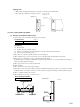
(e) Installation of remote controller ( on the indoor unit )
Attached remote controller may be installed on the indoor unit as shown below. The work can be done on the spot when the
customer asks so or by other reasons.
Refer to the page 176 when it is instralled on the wall.
1) Detach the front panel.
2) Remote controller installation.
● Attach the lower case with the screws (M4 128) accessory.
3) Remote controller wiring.
a) Connect the terminals between the remote controller and the control box as per these wire color codes:[ (X) (red). (Y)
(white), (Z) (biack)], using the wires included in the kit.
b) The wires should have a surplus length of approximately 30 cm. (Necessary when servicing with the front panel
detached.)
c) Strip and solder as shown below when cutting the wire. (Omitting the soldering process may cause looseness of the
wiring.)
Decrine
Trap
Up-and-down bend
Bad
Bad
A
2-Ø3.0
(Holes of tapping screws)
Wiring hole Ø16
84 0.5
Unit: mm
VIEW A
10 ~ 15 mm 10 mm(Stripe and soldering.)