
Specifications


184
Drain test
[Perform this before installing the ornament panel]
● Perform this upon completion of electrical work.
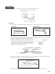
● Gradually introduce 2,000~3,000cc of water as shown below.
● Connect the remote control switch and set to cooling operation. The drain pump will operate with the compressor on.
● Test whether or not the water is draining while listening to the operating sounds of the electric motor for the drain water.
● Check that water is draining smoothly and that there is no water dripping from the connections or other areas.
Forced drain pump operation
● Turn on dip switch (SW5-3) on the PCB of the indoor unit. The drain pump
operates continuously.
● After the test, be sure to turn off the dip switch.
(If the electrical work has not been completed, connect a convex coupling to
the drain pipe to provide a supply port and confirm the draining status of the
piping system.)
Mounting the Panel
1 Open the inlet grille and remove the air block panel from the inside. (Re-
move the 2 screws.)
f) Air bleed should not be provided in any event.
● When it is necessary to raise the drain head, the limitation is up to 600mm below the bottom face of ceiling where the
unit is installed. The distance is the dimension of the pipe which is installed perpendicularly from a point close to the
output for drain pipe connection.
Air block panel
If the electrical work has not been completed, connect a convex joint
in the drain pipe connection to provide a water inlet.
Then, check if water leaks from the piping system and that drain flows
through the drain pipe normally.
()
Pour water into a convex joint
295~325
Drain hose (accessory)
Joints for VP-25 (local procurement)
600 or less
Indoor
unit
Check the drainage condition by using the transparent socket.
Drain hose (provided)
Fill from outlet port
Drain piping connection port
Unit : mm