
Specifications


156
The high pressure control consists of the HP protection, HP-A control, HP-B control and LP control and the order of priority
among them is assigned as HP protection >HP-A > LP > HP-B down > HP-B up.
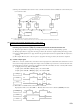
(7) High pressure control
Pressure switch (63H1: 3.24 open/2.65 close MPa) is actuated twice within 45 minutes, the operation is stopped due to the
error and the check and indication (Remote controller: E40, indoor LED-green; repeated flickers, red: dark, outdoor LED-
green; reperted flickers, red; 3 flickers) are performed. In case of initial operation, however, the compressor is stopped and
after a delay of 3 minutes it returns to the normal operation.
(a) HP protection
• If the pressure switch (63H2) is actuated, the outdoor blower is opreated in the Hi mode (for the operations of patterns A1
to C1) or stopped (for the operations of patterns C2 to E2) and, if it is still actuated 2 minutes after a drop of 10 Hz in the
inverter frequency, the frequency is dropped futher by 10 Hz. (Minimum frequency is specified at the partial load of 35
Hz.)
• Operation returns to the normal mode after operating with the frequency control at off
(1)
6 minutes after the 63H2 having been
reset.
Note (1) If the high pressure A control is released,the frequency is raised by 5 Hz and retained at the level for 3 minutes.
The frequency is then raised by 5 Hz at 3-minute intervals till it returns to the normal operation.
(b) HP-A control
1) LP control
If the pressure switch (63L: 1.96 close/2.75 open MPa) is actuated, the operation pattern is changed by one step in the
direction of A1 to E2 so as to raise the low level pressure by controlling the heat exchanger capacity.
2) HP-B down control
If the pressure switch (63H
3: 2.11 close/2.50 open MPa) is actuated, it enters the HP-B down control and the operation
pattern is changed by one step in the direction of E2 to A1 so as to lower the high level pressure by controlling the heat
exchanger capacity.
3) HP-B up control
If the pressure switch (63H
4: 1.86 close/1.67 open MPa) is actuated, it enters the HP-B up control and the operation
pattern is changed by one step in the direction of A1 to E2 so as to raise the high level pressure by controlling the heat
exchanger capacity.
(c) LP,HP-B controls
Table of operation patterns and operations of functional parts
Under these controls, the high and low level pressures are controlled with the solenoid valves, outdoor fan and other so as
to operate the outdoor unit in the optimum condition in accordance with changing load on the indoor unit.
Operation patterns consist of the following 12 types and respective functional parts are controlled per each pattern.
(1) and mean ON and OFF respectively.
(2) When the fan motor FM01 is in the Me mode, the solenoid valve SV3 is interlocked via a relay. (SV3 open)
Notes
A1
A2
B1
B2
B3
C1
C2
D1
D2
D3
E1
E2
Four-way valve
20SS 20SL
Solenoid Valve
SVS SVL SV2 SV3
Fan motor
FM01
HI
HI
HI
HI
Me
HI
Me
Me
HI
HI
HI
HI
FM02
HI
HI
HI
HI
HI
Operation
pattern