
Specifications


152
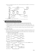
* 1 In the flow in the frame of broken line, operations of operation mode change and thermostat reset are effective and operated immediately upon selection. However,
the compressor ON command is not transmitted.
(i) Control A
a) If the float switch detects the draining, operation is stopped with the error stop (E9 is displayed) and operate the drain
pump.
b) Float switch is checked 3 minutes later on the unit stopped by the error and, if the error persists still, the drain motor is left
at ON but, if the error has already been reset, the drain motor is turned OFF. E9 is displayed till the error is reset.
(ii) Control B
a) If the float switch detects the draining, the expansion valve is closed, the drain motor is turned ON for 3 minutes and, as
10 seconds elapses after the drain motor OFF, the float switch is checked. If the result is normal, the operation stops in the
normal way while, if it is not normal, E9 is displayed, the drain motor is turned ON and the operation stops with the error
stop with the expansion valve being closed completely. (It is left at ON while the draining is detected.)
• Flow chart of drain motor operation
Drain motor ON continues
Float switch operation (Contactor : Open)
Control B
NO
*1
Operation mode?
Control A
Drain motor ON
3 minutes
after float operation?
3 minutes
after float operation?
Drain motor OFF
10 seconds after
drain motor OFF?
Reset
YES
YES
NO
Reset
Float SW?
Float SW?
Operation
Operation
End
Error stop E9
Drain motor 3-minute ON
Error stop E9
Drain motor ON
Compressor OFF
Drain motor OFF
Error stop E9 continues
Float operation?
During compressor ON
Control A
During compressor OFF
Control B
Indoor unit operation mode
OFF
(1)
COOL DRY FAN
(2)
HEAT
Notes (1) Including OFF and error stop during COOL,
DRY, FAN and HEAT.
(2) Including “FAN” operation due to unmatch
of operation mode.
(10) Multiple units control-simultaneous control of 16 unit with one remote controller
(a) Function
Multiple units (even of outdoor different systems, 16 units maximum) can be simultaneously controlled by using a remote
controller. The remote controller is used to set the “operation mode”, and all the unit can be operated and stopped. Thermostat
and protective functions of each unit functions independently.
Note(1)
When part of the group gets out of order (the protective device operates), the relevant unit comes to an abnormal stop, but other normal units keep operating.
(b) Wiring Procedures
(i)
Lay power cable of each unit and signal wire as usual. (Remove the remote control switches from all units excluding only one unit.)
Lay wiring for the remote controller separately from power cable and wires for all other electrical equipment.