
Specifications


748
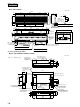
FDC-HKX
(3) Outdoor unit
Models FDCP140HKXE2
Models FDCJ140HKXE2
H4
H3
H2
H1
700 or less
1000 or less
Open
00
0
Not limited
Not limited
Not limited
Not limited
Not limited
Not limited
Not limited
Wall height H2
Wall height H4
Wall height H1
Power supply connecting
terminal block
Signal line connecting
terminal block
Connect of
gas piping
φ19.05(3/4")
Connect of
liquid piping
φ9.52(3/8")
Opening for
exit piping
(φ88)
Opening for
exit wiring
(φ35)
Opening for
exit wiring
(φ50)
Downward outlet hole for
piping and wiring
Anchor bolts
(M10×4pcs.)
Hole for drain
(4-φ20)
Hole for drain
(φ50)
Opening for exit piping
(φ88)
Opening for exit gas piping
(φ39)
Opening for exit liquid piping
(φ25)
Connect of
liquid piping
φ9.52(3/8")
Connect of
gas piping
φ19.05(3/4")
Opening for
exit wiring
(φ50)
suction
L1
L2
L3
L4
Open
Open
0
300 300
500
500
300
(Unit: mm)
Dimensions
Installation
example
Dimensions of refrigerant piping
connecting mouth(plan)
( )
Rear surface
service
spece
L2
L4
L3
170
105
20
1450 50
175
110
70
100
192
112
88
110
309
142
105
80
170
157
102
22
29
532
517
230 176
78
120
47.5
239
595
290
47.5
40
1564015
428
345
131
50
600 690
Wall height H3
Notes (1) Make sure to secure the unit with anchor bolts.
(2) When the strong wind blows, place the unit so that discharge outlet faces
the wind direction with right angle.
(3) Make sure to allow the space of 1 m or more above the unit.
(4) Connect the refrigerant piping (both gas side and liquid side) at local site.
(5) If the wall height H1, H3 of installation example III exceeds the limited value,
make sure the value of L1, L3 are to be as follows.
L1 = H1 - 500
L3 = 300 + (H3 - 700) / 2, however, if L3 exceeds 600, there is no limit for the
wall height H3.