
Specifications


920
OPTION
OPTION
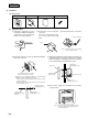
(ii) Wiring connected to the light detection adaptor
Indoor unit terminal block
Wiring
Adapter
u Be careful of the wiring
polarity. Ensure to connect
the wire by matching the
color of the wire with the
color shown on the terminal
block.
CAUTION
Do not connect the wiring to the power source part (220 to 240 V) of the terminal block.
If it is connected, printed board will be damaged.
(iii)
Installation for light detection adaptor
Remove the screw on the side of the light detection adaptor, and sprit it into the upper case and lower case.
Install the receiver with one of the four installation methods
A
or
B
shown below.
A
Installation with enclosed bracket.
Use this method when installing onto a gypsum board (7 to 18 mm), etc.
1 Catch the two protrusion of the enclosed bracket onto the fitting as shown above, and temporarily fix with the screw. (The
bracket has an up/down and front/back orientation. Confirm the top/bottom protrusion positions and the positional relation
of the ø10 holes on the bracket and the installation hole on the lower case with the above drawing.)
2 Insert the end of the installation fitting into the back of the ceiling from the opening, and tighten the screws to fix the bracket
onto the ceiling.
3 Pass the wiring from the rear side through the hole on the lower case.
4 Fit the lower case onto the bracket, and fix the lower case to the bracket using the two installation holes shown above.
(The other four holes are not used.)
5
Follow steps 1 to 3 for ( B ) to complete the installation.
B
Direct installation onto the ceiling with wood screws.
u Use this installation method when the ceiling is wooden, and there is no strength-wise problem in installing directly with
wood screws.
Red White Black