
Specifications


919
OPTION
OPTION
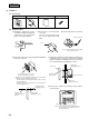
(b) Setting of jumper wire
(i)
Method to prevent the malfunction due to the interference
Perform both procedures 1 and 2.
This setting is made to prevent the interference with other household electric appliances or the interference occurred
when two light detection adaptors are located closely.
1 Setting change of the wireless remote controller
While pressing the
button, press the reset button or load the battery. The setting changes to the interference
prevention setting.
2 Modification of light detection adaptor substrate
Cut the jumper wire (J1) and insulate its both ends.
(ii)
Changeover of Master/slave remote controller
When you use the wireless remote controller as the slave remote controller, cut the jumper wire (J2) on the receiving
substrate of the panel and insulate its both ends.
● Wireless remote
controller
● Light detection adaptor substrate
CAUTION
* When the battery is once removed, the setting returns to the initial setting condition
(setting at factory shipping). Therefore, when the battery has been removed, perform
the above mentioned wireless remote controller setting change work again.
(c) Installation work
Avoid installing the receiver amp in the following positions, as faults may occur or light detection adaptor may be obstructed.
1 Places subject to direct sunlight.
2 Places near heat generating appliances.
3 Places with high humidity levels or where water may come in contact.
4 Places with bumpy surface.
5 Places near fluorescent lights (especially the inverter type) or where light may directly contact the light detection surface.
6 Places hidden by the indoor unit, etc., when looking from the wireless remote controller operation positions.
7 Places subject to the air blow off by the indoor unit.
The following two installation methods can be used to install the light detection adaptor onto the ceiling. Select a method
according to the installation position.
<Installation method>
A
Installstion with enclosed bracket.
B
Direct installation onto the ceiling with wood screws.
(i)
Drilling of the ceiling (ceiling opening)
Drill the light detection adaptor installation holes with the following dimensions at a the ceiling position where wires can
be connected.
A
Installstion with enclosed bracket. 108 mm (H) × 108 mm (W)
B
Direct installation onto with wood screws. 88 mm (H) × 101 mm (W)
MODE TEMP ON/OFF
AIR FLOW FILTER
FAN SPEED
SET
TIMEACL
TIMER
AUTO COOL DRY FAN HEAT
FILTER
°
C
AM
PM
ON
AM
PM
OFF
FAN HI LO
(Master/slave changeover)
"J2"
(Interference prevention)
"J1"
W
H