
Specifications


916
OPTION
OPTION
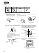
1 Weekly timer 2 Power source kit 3 Installation instructions Manual 4 Pan head screw
M4 × 25 × 2 units
(b) Installation Work
(i) Embed the signal wire (for the
electrical box and the weekly timer)
and the power source wire (for the
power source kit) in advance.
(ii) Remove the cover of the power
source kit.
The cover is not used. The screws
are used to attach the weekly
timer.
(iii) Connect the power source wires.
Cover
Power source wire
Note(1) Confirm the power source voltage,
then correctly connect it.
(v) Attach the weekly timer together with a JIS switch cover
(supplied by the user) to a JIS electrical box (supplied
by the user) with 4 installing screws (accessory). The
box should be firmly secured with the screws.
(iv) Remove the upper case of the weekly timer and attach
the power source kit.
Use the screws that were securing
the cover of the power source kit.
Upper case
Electrical box
(supplied by the user)
Installing screw
4 (accessory)
Power source kit
Switch cover
(supplied by the user)
(vi) Connect the signal wire (terminals A, B) and the
connector CN1.
A
B
CN1
Note(1) Turn on the power source of the weekly timer
at least 2 minutes after the power source of
the unit is turned on.
• Weekly timer is for embedded installation. If it will be installed
separately, install it following the points below.
• The wire between the weekly timer and the power source kit
should be within 4 m.
• When the weekly timer is fixed, make sure to close the hole in
the central upper section.
Hexagonal nut M4
(supplied by the user)
Flat washer M4
(supplied by the user)
Pan head screw
(supplied by the user)
M4 × 12
Power source
wire
Signal wire
Electrical box
(Field supplied)
(4) Installation
(a) Accessories