
Specifications


913
OPTION
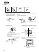
(b) Installation Work
(i) Embed the signal wire (for the electrical
box) and the power source wire (for the
power source kit) in advance.
(ii) Remove the cover of the power
source kit.
The cover is not used. The screws
are used to attach the center console
SLA-2A-E.
(iii) Connect the power source
wires.
Cover
Power source wire
Note: When an external
timer or emergency
stop input is
connected, connect
the accoessorized
3 wire to the local
on-site wires.
Note (1) Confirm the power source
voltage, then correctly
connect it.
(iv) Remove the upper case and attach the power source kit to
the center console.
(v) Secure to the box with the 6 pan head screws.
C
N
1
C
N
2
A B
Use the screws that were securing
the cover of the power source kit.
(vi) Connect the signal wire (terminals A, B) and the connector
(CN1).
CN1
CN2
Signal wire (non-polar)
SW32 (up-ON, down-OFF)
3 Optional wires
(accessory)
Auxiliary wire
If connecting an external timer,
connect the connector CN2.
6 Pan head
screw (6
locations)
8 Cover (accessory)
7 Pan head screw
(4 locations)
8 Cover (accessory)
6 Pan head screw
9 Spring (top only)
Secure so it will face towards you on the left
hand side as shown in the figure
Electrical box
Power source kit
Center console
Lower case
• Even if the 8 cover is not used, the box can be secured with the 6
pan head screws at 2 locations.
• If the lower case is distorted by the box burr, use 8. Secure at
maximum 6 locations. Secure 8 to the box in advance with 7.
Note (1) The center console SLA-2A-E is an embedding type. If separate installation (installing the center console and the power
source kit separately) is inevitable, follow the points below:
● The length of wire between the center console and the power source kit should be within 4 m.
● Make sure to attach the 9 pring provided as an accessory.
• Wait at least two minutes after turning the power on for the unit
before turning the power on for the center console.
Power source
wire
Signal wire
Electrical box
(Field supplied)
CN1
CN2
A B