
Specifications


912
OPTION
OPTION
Signal wire
Center
console
SLA-2A-E
(2) Wiring Connection Diagram
Signal wires
Size: 0.75 mm
2
~ 2.00 mm
2
Wiring materials: Standard wires (use shielded wires if there
is noise)
Maximum extendible length: under 1000 m
Signal wire
Auxiliary wire
Butt terminal
Power source
AC 220 V
or 240 V
{
Power source kit
A
B
SLA2A-E
CN1
CN1
Common
White
Black
(a) When a weekly timer is used:
• When SLA-2A-E is connected with a weekly timer
(SCA-WT-E), special wiring and setting are
unnecessary.
• Cannot be connected with SC-WT-E.
(b) When an external timer input is used:
CN2
3 Optional wire
Demand
Timer
Emergency stop
Common
Black
Yellow
Green
White
Brown
Blue
Red
Input signal condition (level)
(c) Operation/Abnormal output
Demand
Timer
Emergency stop
Common
Common
Orange
Yellow
Green
White
Brown
Blue
Red
SLA2A-E
CN2
CN1
C
Operation output
Abnormal output
Remote control interface (sold separately) (❈1)
• When output signal is used, a
model specific interface (sold
separately) is necessary.
• Wire c shown in the figure
comes with the interface.
(❈1) Remote control interface
SC-RIF-E for SLA-2A-E.
● A maximum of 3 center consoles SLA-2A-E can be
connected in the same network. Also, it may be combined
with center console SLA-1-E. The maximum number of SLA-
1-E that may be connected to the connecting units of SLA-
2A-E is shown in the table below.
SLA-2A-E SLA-1-E
13
22
30
● When using the center console SLA-2A-E, the standard
remote control is not necessary.
However, if wire door cleaner panel is used, a standard
remote control is required.
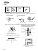
(3) Installation
(a) Accessories (check the following accessories)
1 Center Console 2
Power source kit
3 Optional wires 4
Instruction manual
5
Labels for switch display
6
Pan head screw
7
Pan head screw
8
Cover for installing box
9 Spring
M4 × 20 × 6 units M4 × 10 × 4 units