
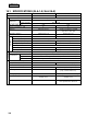
Specifications


910
OPTION
OPTION
4 Remove the upper case of the center console.
Attach the power source kit to the center console.
5 Secure the center console to the JIS electrical box with the 8 pan head
screws.
6 Connect the signal wire (terminals A, B) and the connector (CN1).
7 If more than 3 units of center console SLA-1-E are to be installed within 1
network, conduct the group setting with the supplied 5 screwdriver.
(See (c) for detail.)
8 Reinstall the upper case onto the lower case, and the installation is complete.
Use the screws that were securing
the cover for the power source kit.
Signal wire
(non-polar)
Auxiliary wire
4 Wire for timer
(accessory)
If a commercial timer is used,
connect the connector CN2.
(ii) Separate Installation (Installing the center console
and the power source kit
separately)
1 Remove the cover of the power source lit.
2 Connect the power source wires.
3 Upon shipment, remove the wires which have already been attached,
and connect the 9 wire (accessory) to the terminal board GND of the
power source kit (white wire) and to 5 V (Black wire).
4 Reinstall the cover and secure it with the 0 binding band.
5 Secure the power source kit with the A wood screw in the vicinity of the unit
where maintenance and inspection may be carried out easily.
6 Connect the signal wire and the auxiliary wire to the center console as
described in the “Direct attachment” above.
7 Secure the center console to the wall in the same method as for the standard
remote control.
9 Wire
Power
source
wire
0 Binding band
A Wood screw
No preferred direction for installation.
(c) Unit Number Setting for Contolling Units
● Set the unit numbers to the units controlled by the center
console as follows.
(i) Setting the starting address
(ii) Number setting for the connected units
Note(1) Set the starting address in the range of 00 and 47 because the
maximum number of units that may be installed within 1 network is
48.
Note(1) One center console SLA-1-E can control 16 units. Therefore, the
maximum number of units that may be connected is 16. Also,
because the maximum number of units that may be connected
within 1 network is 48, set the starting address + the number of
connected units in the range ≤ 48.
(iii) Controlling more than 17 units of air conditioners by
center console SLA-1-E
Use multiple units of center console SLA-1-E.
1 A maximum of 6 center consoles SLA-1-E may be connected within a network.
Example 5) Address setting when using 6 center consoles SLA-1-E (a~f).
Starting address
Number of connected units
Unit Number of Controlling Units
a 0 0 0 5 0 0 ~ 0 4
b 0 5 1 5 0 5 ~ 1 9
c 2 0 0 6 2 0 ~ 2 5
d 2 6 0 8 2 6 ~ 3 3
e 3 4 1 0 3 4 ~ 4 3
f 4 4 0 4 4 4 ~ 4 7
2 Unit numbers may be repeated with multiple center consoles SLA-1-E.
Example 6) Address setting when using 3 center consoles SLA-1-E (a~c).
Starting address
Number of connected units
Unit Number of Controlling Units
a 0 0 1 5 0 0 ~ 1 4
b 1 0 1 5 1 0 ~ 2 4
c 2 3 0 6 2 3 ~ 2 8
The unit numbers 10 ~ 14 can be controlled by both a and b, and 23 ~ 24 by
both b and c.
unit of 10 unit of 1
Starting address
unit of 10 unit of 1
0 0
unit of 10 unit of 1
0 5
unit of 10 unit of 1
Number of connected units
unit of 10 unit of 1
0 7
unit of 10 unit of 1
1 6
Set number of the first unit controlled by the center
console SLA-1-E.
Example 1: Case 00 Example 2: Case 05
Set the number of connected units controlled by the
center console SLA-1-E.
Example 3: 7 units Example 4: 16 units
Upper case
8 Pan
head screw
Center console SLA-1-E
Electrical box
Power
source kit
Be careful not to
trap wires
CN1
CN2
see 2 and 3 in
“Direct attachment”
above”