
Specifications


854
FDC-HKX
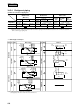
(3) In the case where the unit is exposed to strong wind.
● Face the unit air outlet at a 90 ˚angle from the direction of the wind.
Wind direction
Wind direction
Note (3) When the wall heights H1 and H3 exceed the limited value, keep dimensions for L1 and L3 as shown below.
L1 = H1 – 500
L3 = 300 + (H3–700) / 2
However, there is no limitation in wall height H3 if L3 exceeds 600.
Note (4) The space of 1,500 mm per a series of 8 blower units is required for W4.
(Example : 5HP × 8units in series installation, 10HP × 4 units in series installation)
Note (5) When installing more than 3 rows with the oblique blow in lengthwise, change the blow direction of the group in the central row units,
excluding the both end rows, to the up blow (option). This group blows to the wall and also opposes to the units at the rear in the suction face.
For the example shown below, the uppermost group in the second row falls under the above notes.
Note (6) Install the rack that stores the piping, etc. so that it does not interfere with the airflow entering into the heat exchanger.
Change to the up blow type
(Oblique blow is allowed.)
1st row 2nd row 3rd row
W1
1,500 and
over
800 and
over
Oblique blow
(standard)
Up blow
(option)
W2
800 and
over
800 and
over
W3
1,500 and
over
1,500 and
over
W4
1,500 and
over
1,500 and
over