
Specifications


813
FDC-HKX
8) Places exposed to oil splashes or steam (e.g. kitchens and machine plants.)
Installation and use at such places will incur deteriorations in the performance or corrosion with the heat exchanger or damage
in molded synthetic resin parts.
9) Places where corrosive gas (such as sulfurous acid gas) or inflammable gas (thinner, gasoline, etc.) is generated or remains.
Installation and use at such places will cause corrosion in the heat exchanger and damage in molded synthetic resin parts.
10) Place adjacent to equipment generating electromagnetic waves or high-frquency waves such sa in hospitals. Generated noise
may cause malfunctioning of the controller.
(b) Preparations for installation
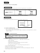
1) Ceiling hole and suspension bolt positions
a) The pattern sheet shrinks or expands as humidity changes, so check the actual size before use.
b) The ceiling hole sizes and suspension bolt sizes are shown in the following figure.
(c) Installation
When rooms have already been ceiled
1) Make holes with the specified ceiling hole size at the installation position.
2) Suspension bolt
•User four M10 or W3/8 suspension bolts (customer orderd parts) and fix each of them so as to withstand a pull-
out load of 50kg/f per bolt.
Note: Note that the suspension bolt pitch center deviates from the panel center.
3) The length of the suspension bolt should be about 160mm from the ceiling surface.
Models
Mark
12345
FDTW28, 45, 56
type
FDTW112, 140
type
FDTW71, 90 type
1015
1260
1730
885
1130
1600
468
590
825
417
540
775
52
57
57
Unit : mm
Dimension table
Center panel
Control box
1 Ceiling hole size
2 Suspension bolt pitch
34
9040
74
5
97 97
640
446
Ceiling hole size
Suspension bolt pitch