
Microcontroller User's Guide

USER’S GUIDE
050396 37/173
38
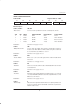
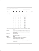
DS5001 CRC REGISTER
Label: CRC Register Address: 0C1H
RNGE3 RNGE2 RNGE1 RNGE0 ––– ––– MDM CRC
Bit Description:
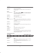
CRC.7–4 RNGE3–0
Determines the range over which a power–up CRC will be performed.
Addresses are specified on 4K boundaries.
Initialization: Reset to 0 on a No V
LI
reset.
Read Access: Can be read at any time.
Write Access: Cannot be written by the application software. Can only be written via the
Bootstrap Loader.
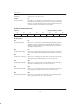
CRC.1 MDM
When set to 1, the bootstrap loader will attempt to use a modem (UART) on
PE4 if CRC is incorrect. This feature is no longer useful following the
obsoletion of the corresponding modem devices.
Initialization: Reset to 0 on a No V
LI
reset.
Read Access: Can be read at any time.
Write Access: Cannot be written by the application software. Can only be written during
Program Load mode.
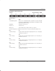
CRC.0 CRC
When set to 1, a CRC check will be performed on power–up or watchdog
timeout. CRC will be checked against stored values. An error will initiate
Program Load mode. This bit will not be present in the DS5002FP as the
device does not support the power–on CRC function.
Initialization: Reset to 0 on a No V
LI
reset.
Read Access: Can be read at any time.
Write Access: Cannot be written by the application software. Can only be written during
Program Load mode.