
Microcontroller User's Guide

USER’S GUIDE
050396 36/173
37
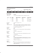
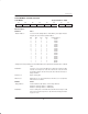
INTERRUPT PRIORITY REGISTER
Label:IP Register Address: 0B8H
D7 D6 D5 D4 D3 D2 D1 D0
RWT – – PS PT1 PX1 PT0 PX0
Bit Description:
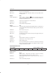
IP.7: RWT
“Reset Watchdog Timer”: When set to a 1, the Watchdog Timer count will be reset and counting will
begin again. The RWT bit will then automatically be cleared again to 0. Writ-
ing a 0 into this bit has no effect.
Initialization: Cleared to a 0 on any reset.
Read Access: Cannot be read.
Write Access: Can be written only by using the Timed Access register.
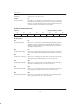
All of the following bits are read/write at any time and are cleared to 0 following any hardware reset.
IP.4: PS
“Serial Port Priority”: Programs Serial Port interrupts for high priority when set to 1. Low priority is
selected when cleared to 0.
IP.3: PT1
“Timer 1 Priority”: Programs Timer 1 interrupt for high priority when set to 1. Low priority is se-
lected when cleared to 0.
IP.2: PX1
“Ext. Int. 1 Priority”: Programs External Interrupt 1 for high priority when set to 1. Low priority is
selected when cleared to 0.
IP.1: PT0
“Timer 0 Priority”: Programs Timer 0 Interrupt for high priority when set to 1. Low priority is se-
lected when cleared to 0.
IP.0: PX0
“Ext. Int. 0 Priority” Programs External Interrupt 0 for high priority when set to 1. Low priority is
selected when cleared to 0.