
Microcontroller User's Guide

USER’S GUIDE
050396 150/173
151
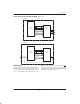
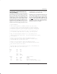
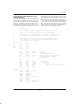
DS2251T/DS2252T RTC BLOCK DIAGRAM Figure 17–6
DS5001
CPU
DS1283
RTC
DS2251T
V
CCO
V
CC
PE1 CE
R/W WE
BA5–0 A5–0
BD7–0
INTB
INTA
INTP
DS5002
CPU
DS1283
RTC
DS2252T
V
CCO
V
CC
PE1 CE
R/W WE
BA5–0 A5–0
BD7–0
INTP
P3.2 (INT0)
MEMORY MAP
In both the DS2251T and DS2252T, the RTC function is
memory mapped. It is accessed using the peripheral
selects. First, the PES bit at MCON.2 must be set to a
logic 1. This will enable the peripheral space in the
MOVX area. The RTC function is mapped under PE1
.
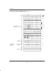
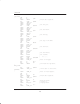
This area begins at address 0000h. The Timekeeping
map consists of 14 time–related registers and 50 bytes
of SRAM. It is illustrated in Figure 17–7.