
Installation manual

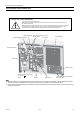


[ III Outdoor Unit Components ]
- 56 -
HWE10040 GB
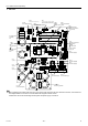
3. INV board
1) Before inspecting the inside of the control box, turn off the power, keep the unit off for at least 10 minutes, and confirm that
the voltage between FT-P and FT-N on INV Board has dropped to DC20V or less.
It takes about 10 minutes to discharge electricity after the power supply is turned off.
SC-L1
Input(L1)
SC-L2
Input(L2)
SC-L3
Input(L3)
IGBT
(Rear)
Bus voltage check
terminal (P)
Note
Bus voltage check
terminal (N)
Note 1
SC-P2
Bus voltage Input(P)
SC-P1
Rectifier diode output (P)
LED1
Lit: Inverter in normal operation
Blink: Inverter error
CN6
Open: No-load operation setting
Short-circuited: Normal setting
CN5V
GND
5VDC output
RSH1
Overcurrent detection
resistor
CN4
GND
(Fan Board)
Serial communication
signal output
CN2
S
erial communication
signal output
GND
17VDC input
SC-V
Inverter output(V)
CNTYP Inverter
board type
SC-W
Inverter output(W)
SC-U
Inverter output(U)
CT22
Current sensor(W)
CT12
Current sensor(U)
C30 C37
Smoothing capacitor
CN1
Bus voltage output
N
P
CT3
Current sensor(L3)