
Installation manual


[ II Restrictions ]
37- 37 -
HWE10040 GB
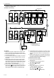
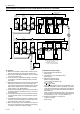
(4) Wiring method
1) Indoor/outdoor transmission line
Daisy-chain terminals M1 and M2 on the terminal block
for indoor-outdoor transmission line (TB3) on the outdoor
units (OC, OS1, OS2) (Note 1), terminals M1 and M2 on
the terminal block for indoor-outdoor transmission line
(TB5) on each indoor unit (IC), and the S terminal on the
system controller. (Non-polarized two-wire)
Only use shielded cables.
a) The outdoor units in the same refrigerant circuit are auto-
matically designated as OC, OS1, and OS2 in the order
of capacity from large to small (if two or more units have
the same capacity, in the order of address from small to
large).
Shielded cable connection
Daisy-chain the ground terminal ( ) on the outdoor
units (OC, OS1, OS2), the S terminal on the terminal
block (TB5) on the indoor unit (IC), and the S terminal on
the system controller with the shield wire of the shielded
cable.
2) Transmission line for centralized control
Daisy-chain terminals M1 and M2 on the terminal block
for transmission line for centralized control (TB7) on the
outdoor units (OC) in different refrigerant circuits and on
the OC, OS1, and OS2 in the same refrigerant circuit.
(Note b)
When both of the following conditions are met, move the
power jumper connector on the control board from CN41
to CN40 on only one of the outdoor units: (1) No power
supply units are connected to the transmission line for
centralized control AND (2) No controllers with a power-
supply function are connected to the system.
Set the central control switch (SW2-1) on the control
board of all outdoor units to "ON."
b) When not daisy-chaining TB7's on the outdoor units in the
same refrigerant circuit, connect the transmission line for
centralized control to TB7 on the OC (Note a). To maintain
centralized control even during an OC failure or a power fail-
ure, daisy-chain TB7 of OC, OS1, and OS2. (If there is a
problem with the outdoor unit whose power jumper was
moved from CN41 to CN40, centralized control is not possi-
ble, even if TB7's are daisy-chained).
Only use shielded cables.
Shielded cable connection
Daisy-chain the S terminal on the terminal block (TB7) on
the outdoor units (OC, OS1, OS2) with the shield wire of
the shielded cable. Short-circuit the earth terminal ( )
and the S terminal on the terminal block (TB7) on the out-
door unit whose power jumper connector is mated with
CN40.
3) MA remote controller wiring
Same as [5] 1.
When 2 remote controllers are connected to the sys-
tem
Same as [5] 1.
Group operation of indoor units
Same as [5] 1.
4) LOSSNAY connection
Connect terminals M1 and M2 on the terminal block
(TB5) on the indoor units (IC) to the appropriate termi-
nals on the terminal block for indoor-outdoor transmis-
sion line (TB5) on LOSSNAY (LC). (Non-polarized two-
wire)
Indoor units must be interlocked with the LOSSNAY unit
using the system controller. (Refer to the operation man-
ual for the system controller for the setting method.) In-
terlock setting from the remote controller is required if the
ON/OFF remote controller alone is connected.
5) Switch setting
Address setting is required as follows.
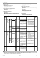
(5) Address setting method
The outdoor units in the same refrigerant circuit are automatically designated as OC, OS1, and OS2.
The outdoor units are designated as OC, OS1, and OS2 in the order of capacity from large to small (if two or more units have
the same capacity, in the order of address from small to large).
Proce-
dures
Unit or controller
Address set-
ting range
Setting method Notes
Factory
setting
1 Indoor
unit
Main unit IC 01 to 50 Assign the smallest address to the
main unit in the group.
To perform a group op-
eration of indoor units
that have different func-
tions, designate the in-
door unit in the group
with the greatest num-
ber of functions as the
main unit.
00
Sub unit Assign sequential numbers starting
with the address of the main unit in
the same group +1. (Main unit ad-
dress +1, main unit address +2, main
unit address +3, etc.)
2 LOSSNAY LC 01 to 50 Assign an arbitrary but unique ad-
dress to each of these units after as-
signing an address to all indoor units.
None of these address-
es may overlap any of
the indoor unit address-
es.
00
3MA
remote
control-
ler
Main
remote
controller
MA No
settings
required.
- Enter the same indoor
unit group settings on
the system controller as
the ones that were en-
tered on the MA remote
controller.
Main
Sub
remote
controller
MA Sub
remote
controller
Settings to be made according to the
remote controller function selection
4 Outdoor unit OC
OS1
OS2
51 to 100 Assign sequential address to the out-
door units in the same refrigerant cir-
cuit.
The outdoor units are automatically
designated as OC, OS1, and OS2.
(Note)
To set the address to
100, set the rotary
switches to 50.
00