
User`s manual


FX communication
Computer link 7
7-14
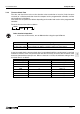
7.6 Character Area Data Transmission
The data shown in the following examples are samples of the data used in character area B when
reading or character area C when writing data. (see section 7.4.1 and 7.4.2)
7.6.1 Bit Device Memory
Bit device memory is handled in 1 bit units (1 point) or in word unit (16 points).
1 ) Bit units (units of 1 point)
When handling bit device memory in bit units, the specified number of devices, in an
increasing order from the specified head device, are represented sequentially from the left,
as “1”(31H) when ON, and as “0”(30H) when OFF.
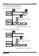
Example: When transmitting the on/off status of five points from M10
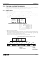
2 ) Word units (units of 16 points)
When handling bit device memory in word units, each word (16 bits, highest bit being first) is
expressed as 4 hexadecimal digits (each of 4 bits) starting with the higher digit. Each digit
being represented by the appropriate ASCII character.
Example: When transmitting the on/off status of 32 points from M16
4DH 30H31H30H30H 35H30H
Head device
M 0 0 1 0
No.of
device
points
0 5
Data
1 0 1 0 1
31H 31H30H31H30H
Indicating M14 is ON
Indicating M12 is ON
Indicating M13 is OFF
Indicating M10 is ON
Indicating M11 is OFF
41H 32H31H42H 33H 44H43H34H
The number of devices is "02" because word units are used.
1010000000000 1111111111111 00000 0
B15 B11B12B13B14 B9B10 B8 B5B6B7 B4 B1B2B3 B15 B11B12B13B14 B9B10 B8 B5B6B7 B4 B1B2B3B0 B0
M
31
M
17
M
18
M
19
M
20
M
21
M
22
M
23
M
24
M
25
M
26
M
27
M
28
M
29
M
30
M
35
M
36
M
38
M
37
M
39
M
40
M
41
M
42
M
43
M
44
M
45
M
46
M
47
M
16
M
33
M
34
M
32
AB DC4321
1:Represents ON
0:Represents OFF
4DH 36H31H30H30H 32H30H
Head device
M 0 0 16
No.of
device
points
0 2
Data
A B 1 2
Data
3 4 C D
Lowest bit
of 2nd word
Head device:
Lowest bit of 1st word