
User`s manual


FX communication
Parallel link 5
5-4
5.3 Example Program
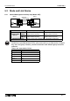
5.3.1 Normal Mode
The ON/OFF status of the inputs X000 to X007 in the master station is output to Y000 to Y007 in
the slave station (
#
). When the calculation result (D0+D2) in the master station is 100 or less,
Y010 in the slave station is turned on (
$
). The ON/OFF status of M0 to M7 in the slave station is
output to Y000 to Y007 in the master station (
(
). The value of D10 in the slave station is set to
the timer (T0) in the master station (
)
).
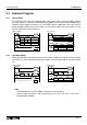
5.3.2 High Speed Mode
When the calculation result (D0+D2) in the master station is 100 or less, Y010 in the slave station
is turned on (
#
). The value of D10 in the slave station is set to the timer (T0) in the master station
(
$
).
Master station
M8000
M8070
M8000
M8000
X010
T0
D500
END
①
②
③
④
Slave station
M8000
M8071
M8000
M8000
X010
END
M10
Y010
①
②
③
④
FNC 20
ADD
FNC 12
MOV
FNC 12
MOV
FNC 12
MOV
K2M800K2X000
D490D2D0
K2Y000K2M900
K2Y000K2M800
M10D490 K100
K2M900K2M0
D500D10
FNC 12
MOV
FNC 12
MOV
FNC 10
CMP
M8000
M8070
M8000
X010
T0
D500
END
M8162
①
②
Master station
Slave station
M8000
M8071
M8000
END
M8162
M10
Y010
X010
①
②
D2D0 D490
D490 K100 M10
D10 D500
FNC 20
ADD
FNC 10
CMP
FNC 12
MOV
Note;
In the normal mode, “FNC 81 PRUN” instruction can be used for
#
.
However, this instruction is only supported for FX
1S
, FX
1N
, FX, FX
2C
, FX
2N
, FX
2NC
programmable controller.