
User`s manual
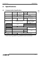
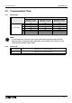
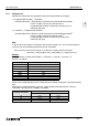


FX communication
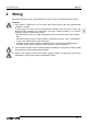
Wiring 3
3-5
3
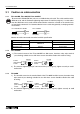
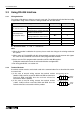
b ) Interlink connection mode (Use interlink serial cross cable)
Setting connection format (BFM #0); b9=1, b8=1
In the interlink connection
mode, data exceeding 512
bytes (upper limit of the receive
buffer in the FX
2N
-232IF) can be
received.
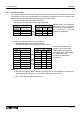
Note:
*1 The FX
2N
-232IF only indicates the status.
*2 In this mode, the request to send (RS) signal functions as the signal to enable receive in
the FX
2N
-232IF.
When receiving data exceeding 512 bytes, the FX
2N
-232IF sets the request to send (RS)
signal to “OFF” and requests the counterpart equipment to suspend the send operation.
When the data saved in the receive buffers is read by the sequence program, the
remaining data can be received.
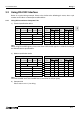
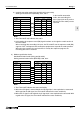
3 ) Modem specification device
Standard RS-232C mode (Using straight cable)
Setting communication format (BFM #0); b9=0, b8=1
Note:
*1 The FX
2N
-232IF indicates the status exclusively.
*2 When the CD signal is not monitored, the CD signal pin is not required to be connected.
With regard to the CD signal, the FX
2N
-232IF indicates the status exclusively.
*3 When the CI signal is not required, the CI signal pin is not required to the connected. With
regard to the CI signal, the FX
2N
-232IF indicates the status exclusively.
Programmable Controller Side
Signal
name
RD (RXD)
SD (TXD)
RS (RTS)
FX
2N
-232IF
2
3
7
RS-232C Device Side
Signal
name
2
3
7
9-pin
D-SUB
25-pin
D-SUB
3
2
4
CS (CTS)
ER (DTR)
8
4
8
4
5
20
6
5
6
7
DR (DTR)
SG (GND)
6
5
RD (RXD)
SD (TXD)
RS (RTS)
CS (CTS)
ER (DTR)
DR (DTR)
SG (GND)
*1 *1
*2 *2
Programmable Controller Side
Signal
name
RD (RXD)
SD (TXD)
RS (RTS)
FX
2N
-232IF
2
3
7
RS-232C Device Side
Signal
name
2
3
7
9-pin
D-SUB
25-pin
D-SUB
3
2
4
CD (DCD)
CS (CTS)
ER (DTR)
1
8
4
1
8
4
8
5
20
6
5
6
7
DR (DTR)
SG (GND)
6
5
RD (RXD)
SD (TXD)
RS (RTS)
CD (DCD)
CS (CTS)
ER (DTR)
DR (DTR)
SG (GND)
*1 *1
*2 *2
9 22CI (RI) 9 CI (RI)
*3 *3