USER’S MANUAL FX COMMUNICATION (RS-232C, RS-485, RS-422) RS-232C FX-232ADP FX0N-232ADP FX2NC-232ADP FX1N-232-BD FX2N-232-BD FX2N-232IF RS-485 FX-485ADP FX0N-485ADP FX2NC-485ADP FX1N-485-BD FX2N-485-BD FX-485PC-IF RS-422 FX1N-422-BD FX2N-422-BD
FX communication Foreword • This manual contains text, diagrams and explanations which will guide the reader in the correct installation and operation of the communication facilities of FX series. It should be read and understood before attempting to install or use the unit. • Further information can be found in the respective manual of each programmable controller.
FX communication FX COMMUNICATION (RS-232C, RS-485, RS-422) USER’S MANUAL Manual number : JY992D69901 Manual revision : E Date : April 2003 Brand and product names described by/in this manual are trademarks or registered trademarks of the irrespective owners.
FX communication ii
FX communication FAX BACK Mitsubishi has a world wide reputation for its efforts in continually developing and pushing back the frontiers of industrial automation. What is sometimes overlooked by the user is the care and attention to detail that is taken with the documentation. However, to continue this process of improvement, the comments of the Mitsubishi users are always welcomed. This page has been designed for you, the reader, to fill in your comments and fax them back to us.
FX communication iv
FX communication Guidelines for the Safety of the User and Protection of the programmable controllers This manual provides information for the use of the FX series communication unit. The manual has been written to be used by trained and competent personnel.
FX communication • Under no circumstances will Mitsubishi Electric be liable responsible for any consequential damage that may arise as a result of the installation or use of this equipment. • All examples and diagrams shown in this manual are intended only as an aid to understanding the text, not to guarantee operation. Mitsubishi Electric will accept no responsibility for actual use of the product based on these illustrative examples.
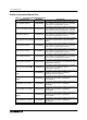
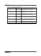
FX communication Further Information Manual List Table 1: Further Information Manual List Manual name Manual No. Description FX1S Hardware Manual This manual contains written hardware explanation of JY992D83901 wiring, installation and specification, etc. regarding the FX1S Series programmable controller. FX0 / FX0N Hardware Manual This manual contains written hardware explanation of JY992D47501 wiring, installation and specification, etc. regarding the FX0 and FX0N Series programmable controllers.
FX communication Table 1: Further Information Manual List Manual name Manual No. Description FX2N-485-BD Hardware Manual This manual contains written hardware explanation of JY992D73401 installation and specification regarding the FX2N-485-BD. FX2N-422-BD User’s Guide This manual contains written hardware explanation of JY992D66101 installation and specification regarding the FX2N-422-BD.
FX communication Table of Contents Further Information Manual List ................................................................... vii 1. Introduction ............................................................................................. 1-1 1.1 Abbreviations, Generic Names and Terms Used in This Manual ..........................1-1 1.2 Communication Types ...........................................................................................1-2 1.3 System Configuration .....................
FX communication 4.2 Setting....................................................................................................................4-3 4.2.1 Setting the Station No. (D8176) ................................................................................................ 4-3 4.2.2 Setting the Total Number of Slave Stations (D8177) ............................................................... 4-3 4.2.3 Setting the Refresh Range (D8178)............................................................
FX communication 8. Commands.............................................................................................. 8-1 8.1 Batch Read of Bit Device (BR command)..............................................................8-2 8.2 Batch Read of Word Device (WR command) ........................................................8-3 8.3 Batch Write of Bit Device (BW command) .............................................................8-5 8.4 Batch Write of Word Device (WW command).......................
FX communication 10.2.13 Send Sum Result .......................................................................................... 10-11 10.2.14 Receive Sum Result ...................................................................................... 10-11 10.2.15 Time from CS ON to Send Start .................................................................... 10-12 10.2.16 Time from Completion of Actual Send to RS OFF (completion flag ON) ...... 10-12 10.2.
Introduction 1 FX communication 1. Introduction 1 1.
FX communication 1.2 Introduction 1 Communication Types The FX Series supports the following 5 types of communication. 1 ) N:N network Data transfer with FX 2N , FX 2NC, FX 1N , FX 1S , FX 0N programmable controllers can be performed on a N:N basis. They can link data of a small-scale system if using this network. For the system configuration please refer to subsection 1.2.
Introduction 1 FX communication 1.3 System Configuration 1 For programming protocol refer to chapter 11. 1.3.1 N:N Network FX PLC RS-485 communication equipment FX PLC RS-485 communication equipment FX PLC RS-485 communication equipment FX PLC RS-485 communication equipment FX PLC RS-485 communication equipment Up to eight FX series programmable controllers can be connected.
Introduction 1 FX communication 2 ) FX1N (Shielded twisted-pair cable) #, $ Using interface FX1N-485-BD FX1N Extension distance Max. 50m (164' 0") FX1N-CNV-BD + FX0N-485ADP FX1N-CNV-BD + FX2NC-485ADP Max. 500m (1640' 5") *2 *2 When including an FX1N-485-BD in the system configuration, thais, total extension distance has a max of 50m (164' 0"). 3 ) FX1S (Shielded twisted-pair cable) #, $ Using interface FX1N-485-BD FX1S Extension distance Max.
Introduction 1 FX communication 1.3.3 Computer Link 1 ) In the case of 1:N connection using RS-485 (RS-422) 1 Computer RS-232C RS-485(RS-422) FX-485PC-IF FX2NC-485ADP, FX0N-485ADP FX0N,FX2NC FX2N + FX2N-CNV-BD, FX1S + FX1N-CNV-BD, FX1N + FX1N-CNV-BD FX2, FX2C FX2N + FX2N-485-BD, FX1S + FX1N-485-BD, FX1N + FX1N-485-BD FX-485ADP A series PLC + A(1S)J71UC24 Up to sixteen FX series programmable controllers can be connected.
Introduction 1 FX communication 1.3.
Specifications 2 FX communication 2. Specifications 2.1 Communication Specification Transmission standard Transmission distance Number of stations Communication method Data length Parity Stop bit Baud rate (bps) Header character Terminator character Control line 2 Computer link N:N network Parallel link No protocol communication (dedicated protocol) Conforming to Conforming to RS-485 Conforming to RS-485 and RS-422 or RS-485 and RS-422 RS-232C RS-485(RS-422): Max. 500m(1640' 5") Max.
Specification 2 FX communication 2.2 Communication Time 2.2.
Specifications 2 FX communication 2.2.3 Computer link Calculations to determine the approximate time until communication is complete.
Specification 2 FX communication MEMO 2-4
FX communication 3. Wiring 3 Wiring Terminal layout when using a communication unit, please refer to the individual units manual. Common 1 ) This system is designed to read and write data (forced on/off) while the programmable controller is running. If abnormal data is written to the programmable controller, due to effects of noise, the programmable controller may malfunction and cause machine trouble or an accident. Therefore, observe the following cautions.
Wiring 3 FX communication 3.1 Caution on cable selection 3.1.1 FX1N-485-BD, FX2N-485-BD, FX2NC-485ADP To connect the RS-485(RS-422) unit, use a shielded twist-pair cable. The cable model must be AWG 26 to 16, and the maximum tightening torque must be 0.6 N%m (6 kgf%cm). If a cable other than the AWG 26 to 16 is used, normal communication cannot be assured as the terminal may be imperfectly contacted. It is recommended to insert a cable integrated by a crimping tool into the terminal.
Wiring 3 FX communication 3.2 Using RS-232C Interface Below is a typical wiring example. Please wire similar to the following pin name, when a pin number on the side of a counterpart machine differs. 3.2.
Wiring 3 FX communication 3.2.2 Using FX2N-232IF The signal wiring of the RS-232C equipment varies depending on the RS-232C connection specifications. Check the specifications of the RS-232C equipment used, then connect the signals correctly. Representative wiring examples are shown below.
Wiring 3 FX communication b ) Interlink connection mode (Use interlink serial cross cable) Setting connection format (BFM #0); b9=1, b8=1 In the interlink connection P rogram m able C ontroller S ide R S -232C D evice S ide mode, data exceeding 512 S ignal S ignal 9-pin 25-pin bytes (upper limit of the receive F X 2N -232IF nam e nam e D -S U B D -S U B buffer in the FX2N-232IF) can be S D (T X D ) 3 S D (T X D ) 3 2 received.
Wiring 3 FX communication 3.3 Using RS-485 Interface 3.3.1 Wiring Selection The wiring of RS-485 can either be one-pair or two-pair. The wiring method is decided according to application usage. Please select the wiring method from the table below. Usage One-pair wiring Two-pair wiring &*2 ' Full-duplex communication *3 × ' It is necessary to set the message wait time to 70 ms or less. × ' It is not necessary to set the massage wait time to 70 ms or less.
Wiring 3 FX communication 3.3.3 One-pair Wiring RS-485 unit *4 FX2NC-485ADP FX1N-485-BD,FX2N-485-BD A series programmable controller's computer link unit Station No. 0 Station No. 1 Station No.
Wiring 3 FX communication 3.3.4 Two-pair Wiring RS-422/RS-485 unit *4 R*1 R*1 FX2NC-485ADP FX1N-485-BD,FX2N-485-BD FX (0N)-485ADP A series programmable controller's computer link unit Station No. 0 Station No. 1 Station No.
Wiring 3 FX communication 3.4 Parallel Link 3.4.1 FX2N(1N)-485-BD and FX0N-485ADP 1 ) One-pair Wiring Terminating resistor 110Ω FX2N-485-BD FX1N-485-BD FX0N-485ADP SDA SDA SDB SDB RDA RDA RDB RDB SG LINK SG 3 Terminating registor 110Ω FG *1 Note: *1 Connect the terminal FG to the ground terminal of a programmable controller grounded with a resistance of 100Ω or less (Class D grounding).
Wiring 3 FX communication 3.4.2 FX0N-485ADP and FX0N-485ADP 1 ) One-pair Wiring Terminating resistor 110Ω FX0N-485ADP FX0N-485ADP SDA SDA SDB SDB RDA RDA RDB RDB LINK SG LINK SG FG FG *1 Terminating resistor 110Ω Note: *1 Connect the terminal FG to the ground terminal of a programmable controller grounded with a resistance of 100Ω or less (Class D grounding).
Wiring 3 FX communication 3.4.
Wiring 3 FX communication 3.4.4 FX2NC-485ADP and FX0N-485ADP 1 ) One-pair Wiring FX2NC-485ADP FX0N-485ADP SDA SDA SDB SDB RDA RDA RDB RDB Terminating resistor 110Ω Terminating resistor 110Ω LINK SG SG FG *1 Note: *1 Connect the terminal FG to the ground terminal of a programmable controller grounded with a resistance of 100Ω or less (Class D grounding).
Wiring 3 FX communication 3.4.
Wiring 3 FX communication 3.4.
Wiring 3 FX communication 3.4.7 FX2-40AW and FX2-40AW FX2-40AW FX2-40AW SA SA SB SB SG *1 SG *1 Note: *1 Connect the terminal SG to the terminal SG of the basic unit. Two SG terminals are connected to each other internally. 3 3.4.8 FX2-40AP and FX2-40AP FX2-40AP FX2-40AP T T R R Note: • " " indicates an optical connector. Keep optical connectors away from cabling carrying high loads. Output terminals (Y000 to Y003) located near optical connectors must have light loads connector.
Wiring 3 FX communication MEMO 3-16
N:N network 4 FX communication 4. N:N Network For diagnostics, please refer to chapter 12. 4.1 Related Flags and Data Registers 4.1.
N:N network 4 FX communication 4.1.2 Data Registers Data Registers Attribute FX0N, FX1S Name FX1N, FX2N, FX2NC Description Response type R D8173 Station No. Saves its own station No. M, L R D8174 Total number of slave stations Saves total number of slave stations M, L R D8175 Refresh range Saves refresh range M, L W D8176 Station number setting Sets its own station No.
N:N network 4 FX communication 4.2 Setting N:N settings become valid when the program is run or when the power of the programmable controller is turned ON. 4.2.1 Setting the Station No. (D8176) Set a value 0 to 7 to the special data register D8176. Set value 0 1 to 7 4.2.2 Description Master station Slave station No. Example: 1 is slave station No.1, 2 is slave station No.2 4 Setting the Total Number of Slave Stations (D8177) Set a value 1 to 7 to the special data register D8177.
N:N network 4 FX communication 4.2.3 Setting the Refresh Range (D8178) Set a value 0 to 2 to the special data register D8178. (Default = 0) This setting is not required for the slave station. The devices used in each pattern are occupied by all the stations for the N:N network.
N:N network 4 FX communication 2 ) In the case of pattern 1 (FX1N, FX2N, FX2NC) Device No. Station No. Bit device (M) Word device (D) 32 points 4 points No.0 M1000 to M1031 D0 to D3 No.1 M1064 to M1095 D10 to D13 No.2 M1128 to M1159 D20 to D23 No.3 M1192 to M1223 D30 to D33 No.4 M1256 to M1287 D40 to D43 No.5 M1320 to M1351 D50 to D53 No.6 M1384 to M1415 D60 to D63 No.7 M1448 to M1479 D70 to D73 4 3 ) In the case of pattern 2 (FX1N, FX2N, FX2NC) Device No. Station No. 4.2.
N:N network 4 FX communication 4.2.6 Program Used for Setting 0 M8038 FNC 12 MOV K 0 D8176 Station No.
N:N network 4 FX communication 4.3 Example Program 4.3.1 System Configuration Master station (No.0) FX 2N 4.3.2 Slave station (No.2) FX 2N FX 2N -485-BD • • • Slave station (No.1) FX 2N -485-BD FX 2N -485-BD 4 Refresh range: 32 bit devices and 4 word devices (Pattern 1) Retry count: 3 times Comms time-out: 5 (50 ms) Operations The following operations are performed in the system configuration above.
N:N network 4 FX communication 4.3.3 Example of Setting Program For the setting program of the master station and the stations Nos.1 and 2, refer to the program below. Master station Slave station No.1 Slave station No.2 D8176 K0 K1 K2 Station No. D8177 K2 Total slave station : 2 stations D8178 K1 Refresh range : Pattern 1 D8179 K3 Retry count : 3 times (default) D8180 K5 Comms time-out : 50 ms (default) 0 4.3.
N:N network 4 FX communication 4.3.
N:N network 4 FX communication b ) Program of slave station No.
N:N network 4 FX communication c ) Program of slave station No.
N:N network 4 FX communication MEMO 4-12
Parallel link 5 FX communication 5. Parallel link Data transfer with FX2N, FX2NC, FX1N, FX, FX2C programmable controllers can be performed on a 1:1 basis for 100 auxiliary relays and 10 data registers. Data transfer with FX 1S , FX 0N programmable controller can be performed on a 1:1 basis for 50 auxiliary relays and 10 data registers. For system configuration, refer to subsection 1.2.2. 5.
Parallel link 5 FX communication 5.2 Mode and Link Device 5.2.
Parallel link 5 FX communication 5.2.
Parallel link 5 FX communication 5.3 Example Program 5.3.1 Normal Mode The ON/OFF status of the inputs X000 to X007 in the master station is output to Y000 to Y007 in the slave station (#). When the calculation result (D0+D2) in the master station is 100 or less, Y010 in the slave station is turned on ($). The ON/OFF status of M0 to M7 in the slave station is output to Y000 to Y007 in the master station ((). The value of D10 in the slave station is set to the timer (T0) in the master station ()).
Communication format 6 FX communication 6. Communication format (D8120) This chapter explains setting the communication between no protocol communication (RS instruction) and computer link. For the RS instruction, refer to Section 9. For computer link, refer to Sections 7 and 8. 6.1 What Is Communication Format? The communication format decides the communication setting (data length, parity, and baud rate, etc.) between computer link and no protocol communication (RS instruction).
Communication format 6 FX communication 6.3 Communication Format (D8120) Bit No.
Communication format 6 FX communication 6.4 Example of setting program When setting the contents shown on the left, perform programming as follows.
Communication format 6 FX communication MEMO 6-4
Computer link 7 FX communication 7. Computer Link This chapter explains the details and methods of specifying dedicated protocol used for linking of the FX programmable controller and computer. The dedicated protocol is available in two types, format 1and format 4 (the format names conform to the dedicated protocols used in the computer link unit of the A series programmable controller).
Computer link 7 FX communication 3 ) Programmable controller sends data to the computer. Computer RS-232C (6)Data OS* 485PC-IF RS-485 (5) Programmable controller 485ADP (4) Data OS* Program On-demand data (7) Write Data Comn. Prog. Data(3) (2)Read (1)Send Device memory,etc. request+ data write *OS (operating system) is the software for operating (or using) effectively the resources such as the CPU, memory, terminal, file and network.
FX communication 7.2 Information Needed Before Programming 7.2.1 Programmable Controller Operation Computer link 7 The operation and the scan time of programmable controller using computer link is as follows. While the programmable controller is running, access requests to the programmable controller from the computer are processed on every END processing. The processing of Send or Receive data is performed using interrupts.
Computer link 7 FX communication 7.3 How to Read a Control Protocol Diagram 1 ) When the computer reads data from the programmable controller (computer ← programmable controller) A Computer E N Q C A C K Data S T X Programmable controller Data Data B a ) Areas A and C indicate transmission from the computer to the programmable controller. b ) Area B denotes transmission from the programmable controller to the computer.
Computer link 7 FX communication 7.4 Basic Formats of Dedicated Protocol There are two formats for the dedicated protocol; which may be selected by setting special data register D8120(see chapter 6). The difference between these two formats is whether CR + LF is added to each block or not. The protocols are format 1 and format 4. (The format names conform to the computer link unit for the A series programmable controller.) Basic format of transmitted data. Control code Station No. PLC No.
Computer link 7 FX communication 7.4.1 Control Protocol Format 1 Description Control protocol * or Sum check code E T X Character or area B PLC No. Station No. S T X Programmable controller PLC No. Station No. A C K Sum check code area A Character Message wait time Command PLC No. Computer Station No. E N Q To read data from the PLC to the computer PLC No. Station No. N A K Transmission sequence PLC No. Station No. ACK PLC No. Error code Station No.
Computer link 7 FX communication 7.4.2 Control Protocol Format 4 Description Control protocol L C F R L C or L C F R Sum check code E T X L C F R PLC No. Station No. N A K Error code * Character or area B PLC No. Station No. S T X Programmable controller F R F R Station No. A C K L C Sum check code Character area A Message wait time Command PLC No. Computer Station No. E N Q To read data from the PLC to the computer PLC No. * PLC No. Station No.
Computer link 7 FX communication 7.4.3 Control Protocol Parts Explained This is to explain the content of data set in each control procedure. 1 ) Control codes The control codes are listed below.
Computer link 7 FX communication 2 ) Station number The station number is the number provided at the programmable controller in order to determine which programmable controller the computer accesses. In the FX series programmable controller, the station number is set by the special data register D8121(special D8121 hereinafter). The setting range is 00H to 0FH. In the case of FX0N series turn on M8120 when using the special D8121.
Computer link 7 FX communication 5 ) Message wait This is a delay time required by some computers to switch between send and receive states. The message wait time determines the minimum delay before the programmable controller sends data after receiving a message from the computer. Set the wait time according to the computer specifications. The message wait time may be set between 0 to 150 ms in 10 ms increments. The value is set using a single ASCII character (“0 to “F”) representing 0H to FH (0 to 15).
Computer link 7 FX communication 7.4.4 Time-out Check Time The time out check time refers to the duration after termination of receive (final character received) of a failed transmission from the computer to the programmable controller, until the send sequence is initialized. This check time is specified as follows depending on the model and version of the programmable controller.
Computer link 7 FX communication 7.5 Communication Timing Chart 7.5.1 Reading Data from Programmable controller ACK ENQ Computer Wait(TW) T3 T4 T5 Interface STX Read process Programmable controller T0 T1 More than two-scan delay is needed. This time becomes 0 when the message wait time is not set or when the wait time is less than the processing time needed by the programmable controller.
Computer link 7 FX communication 7.5.3 Communication Time This is to explain the method of calculating the approximate time until all communication is over. For the locations of T0 to T4, see the previous page.
Computer link 7 FX communication 7.6 Character Area Data Transmission The data shown in the following examples are samples of the data used in character area B when reading or character area C when writing data. (see section 7.4.1 and 7.4.2) 7.6.1 Bit Device Memory Bit device memory is handled in 1 bit units (1 point) or in word unit (16 points).
Computer link 7 FX communication 7.6.2 Word Device Memory When handling word device memory, each word is expressed as 4 hexadecimal digits (each of 4 bits) starting with the higher digit. Each digit being represented by the appropriate ASCII character. Example 1) When showing the contents of data registers D350, D351 No.
Computer link 7 FX communication 7.7 Commands and Device Ranges 7.7.1 Commands Maximum No. of units per communication Command Description Bit unit Device memory Batch read Word unit Bit unit Batch write Word unit Bit unit Test (select write) Word unit Symbol ASCII code BR 42H, 52H WR BW WW BT WT FX0N, FX1S Reads a group of bit devices (X, Y, M, 54 points S, T, C), result is in units of 1 device.
Computer link 7 FX communication 7.7.2 Device specification ranges The following is the device and device number range that can be used in the access of device memory. Each device is composed of five characters. Device (1 character, 2 characters with timer and counter) + device number (4 characters, 2 characters with timer and counter) = 5 characters.
Computer link 7 FX communication 7.8 Example Computer Program for Loopback Test This is an example of a BASIC program for communication of the computer link using a computer, programmable controller 485PC-IF, and 485ADP. (not used outside Japan.) Pleas see loopback test command see section 8.11.
FX communication Computer link 7 190 HED$ = LEFT$(BUF$.
Computer link 7 FX communication 3 ) Operation a ) Start the computer program. b ) Send four characters “ABCD” from the computer to the FX programmable controller. c ) The FX programmable controller returns the four characters “ABCD” back to the computer. d ) The computer compares the data received from the programmable controller and the original sent data, and displays a result message. 4 ) List of result messages Message Received data is normal. Remedy Data sending and receiving is normal.
Commands 8 FX communication 8. Commands This chapter describes the structure and gives examples for each command of the dedicated protocol. See also Chapter 7 “Communication using Dedicated Protocols”. The reference pages for command are given below. Command Description Section BR Bit devices read in units of 1 point. 8.1 WR Bit devices read in units of 16 points, or word devices read in units of 1 point. 8.2 BW Bit devices written in units of 1 point. 8.
Commands 8 FX communication 8.1 Batch Read of Bit Device (BR command) 1 ) Command specification Protocol format 1 is shown. Batch read command (bits) Character area A PLC No. E T X Data of the specified devices Sum check code PLC No. S T X Station No. Specifies the range of devices to be read. Station No. (5 characters) (2 characters, hexadecimal) "0" (30H) indicates OFF. "1" (31H) indicates ON. A C K Number of devices Sum check code Message wait time B R PLC No. E N Q Station No.
Commands 8 FX communication 8.2 Batch Read of Word Device (WR command) 1 ) Command specification Protocol format 1 is shown. Batch read command (words) Character area A PLC No. E T X Data of the specified devices Sum check code PLC No. S T X Station No. Specifies the range of devices to be read. Station No. (5 characters) (2 characters, hexadecimal) A C K Number of devices Sum check code Message wait time W R PLC No. E N Q Station No.
Commands 8 FX communication b ) Example 2 To read the present value of two points, T123 and T124, at station No.5.
Commands 8 FX communication 8.3 Batch Write of Bit Device (BW command) 1 ) Command specification Protocol format 1 is shown Character area A Batch write command (bits) Number of devices Data of the (5 characters) (2 characters, specified hexadecimal) devices Sum check code Message wait time B W PLC No. E N Q PLC No. Station No. Specifies the range of devices to be written. "0" (30H) indicates OFF. "1" (31H) indicates ON. ACK Programmable controller Station No.
Commands 8 FX communication 8.4 Batch Write of Word Device (WW command) 1 ) Command specification Protocol format 1 is shown Batch write Command (words) Head device Number of devices Data of the (5 characters) (2 characters, specified devices hexadecimal) Sum check code Message wait time B R PLC No. Station No. E N Q PLC No. ACK Specifies the range of devices to be read. One word device requires four hexadecimal digits. Therefore,one word is expressed using four characters. Station No.
Commands 8 FX communication b ) Example 2 To write to data to two points, D0 and D1, at station No.0 (with message wait time set to 0 ms). Computer Programmable controller E N 0 0 Q F F WW 0 D 0 0 0 0 0 2 1 2 3 4 A C D 7 F 9 05H 30H 30H 46H 46H 57H 57H 30H 44H 30H 30H 30H 30H 30H 32H 31H 32H 33H 34H 41H 43H 44H 37H 46H 39H The sum check is calculated over this range A C 0 5 K F F 06H 30H 30H 46H 46H 1234H(hexadecimal) to D0: indicates to write 4660 in decimal.
Commands 8 FX communication 8.5 Test of Bit Device (BT command) 1 ) Command specification Protocol format 1 is shown Test command (selective write,bits) (2 characters, hexadecimal) (5 characters) Device (5 characters) Sum check code Device Set/reset Number of devices Set/reset Message wait time B T PLC No. Station No. E N Q PLC No. 1 character "0" (30H) indicates reset (OFF) "1" (31H) indicates set (ON) Station No.
Commands 8 FX communication 8.6 Test of Word Device (WT command) 1 ) Command specification Protocol format 1 is shown. Test command (selective write,word) Number of devices Device Device Device Device (2 characters, hexadecimal) (5 characters) (4 characters) (5 characters) (4 characters) Sum check code Message wait time W T PLC No. E N Q Station No. PLC No. Station No. One word device requires four hexadecimal digits. Therefore,one word is expressed using four characters.
Commands 8 FX communication 8.7 Remote RUN/STOP (RR, RS commands) 8.7.1 Operation of Remote RUN/STOP When remote RUN/STOP is requested from the computer, the programmable controller forced run mode, and the special auxiliary relays M8035, M8036, M8037 are controlled as follows. • Remote RUN When remote RUN (RR command) is requested, M8035 and M8036 are set ON at the programmable controller, and forced RUN mode becomes active; the programmable controller switching to RUN.
Commands 8 FX communication 8.7.3 Control Specification and Examples of Remote RUN/STOP 1 ) Control specification Protocol format 1 is shown. Programmable controller remote run command: "RR" Programmable controller remote stop command: "RS" Sum check code Message wait time PLC No. Station No. E N Q PLC No. A C K Station No. Computer Programmable controller RR or RS Notes • The station number, PC (PLC) number, number of devices, and sum check code are expressed in hexadecimal.
Commands 8 FX communication 8.8 Reading The Programmable Controller Type (PC command) 8.8.1 Type Codes Programmable controller type Type code (hex.) Programmable controller type Type code (hex.
Commands 8 FX communication 8.8.2 Control Specification and Example 1 ) Control specification Protocol format 1 is shown. Programmable controller type name read command E T X (2 characters) Sum check code PLC No. S T X Station No. PC type name PLC No. A C K Character area B Station No. Sum check code Message wait time P C PLC No. Station No.
Commands 8 FX communication 8.9 Global Function (GW command) This function is to turn on and off the global operation flag at all stations in the multidrop link. For an FX series programmable controller this is special auxiliary M8126, and for an A series programmable controller, it is Xn2 of the computer link unit. This function can be used for initialization, resetting or simultaneous star t/stop of all programmable controller stations. 8.9.
Commands 8 FX communication 8.10 On-demand Function Data transmission between the computer and programmable controller is usually initiated by the computer only. The on-demand function is used if there is a need to transmit data from the programmable controller to the computer. The range of data registers containing the data to be sent is specified in special data registers.
Commands 8 FX communication 8.10.2 On-demand Control Protocol 1 ) Control protocol programmable controller On-demand data transmission Set the word/byte data format …… Set on/off special M8129. ON: byte units(8bits), OFF: word units(16bits) Set the on-demand data …… Write the data to be transmitted into data registers. Reset the on-demand error flag …… Turn off on-demand error flag special M8128. (If special M8128 is ON, on-demand can not be started.
Commands 8 FX communication 3 ) On-demand request time chart. • When the computer is transmitting data Computer E N Q b) On-demand data A C K c) Programmable controller S T X On-demand execution flag M8127 Start on-demand, Programmable writing of the oncontroller demand data length a) a ) When on-demand is requested, the on-demand execution signal (special M8127) is immediately turned on.
Commands 8 FX communication 8.10.3 Specification and Example of On-demand 1 ) Command specification Protocol format 1 is shown. Added by programmable controller Sum check code E T X PLC No. S T X Transmission data ON Special auxiliary relay M8127 Programmable controller Station No. Computer Programmable controller OFF Write processing On-demand data is set, the head address is written to D8127 and the data length is written to D8128.
Commands 8 FX communication 2 ) Specification Example 1 To transmit the data stored in data registers D100 and D101 from the programmable controller (when the station number is 0, and data is specified in word units) The PLC number "FE" is automatically added by the programmable controller.
Commands 8 FX communication 3 ) Specification Example 2 To transmit the data stored in data registers D100 and D101 from the programmable controller (when the station number is 0, and data is specified in byte units) The PC number "FE" is automatically added by the programmable controller Computer Programmable controller S T 0 0 X F E 3 4 1 2 7 8 5 6 E T 9 2 X 02H 30H 30H 46H 45H 31H 32H 33H 34H 37H 38H 35H 36H 03H 39H 32H M8127 Programmable controller On-demand command Write processing ➀ D8127
Commands 8 FX communication 8.11 Loopback Test The loopback test is the function for testing if communication between the computer and programmable controller is operating as normal or not. 1 ) Command Specification Protocol format 1 is shown. Loopback test command Data (designated No. characters) Sum check code No. Characters Message wait time T T PLC No. Station No. E N Q 2 characters (hexadecimal) Sum check code Data (same data as character A area) E T X No. Character PLC No.
Commands 8 FX communication MEMO 8-22
RS instruction 9 FX communication 9. RS instruction This section refers to the RS instruction. For target devices, refer to the application instruction manual of each programmable controller. 9.1 Function and Operation 9.1.1 Send and Receive Program An RS instruction sends and receives serial data via the RS-232C port (optional equipment).
RS instruction 9 FX communication Operating Conditions and Format Set Content The programmable controller can change from using no protocol communication to programming protocol (and back) by manipulating the RS instruction and Register D8120 and shown below. 1 ) With the RS instruction ON, move the data options shown below into the Register D8120 to use no protocol communication.
RS instruction 9 FX communication 9.1.2 Operation of RS Instruction An RS instruction specifies the head address and the number of points of the send data sent from a programmable controller as well as the head address for receive data save destination and the maximum acceptable number of points of receive data. The data send/receive sequence using an RS instruction is described below.
FX communication 9.1.3 RS instruction 9 Related Flags and Data Registers 1 ) Send request When M8122 is set by a pulse instruction in the receive wait status or the receive completion status, data from D200 to D0 is sent. When send is completed, M8122 is automatically reset. When the RS instruction drive input X010 is turned on, the programmable controller is set to the receive wait status. Note: In the FX, FX2C, FX0N, FX1S, FX1N and earlier versions than V 2.
RS instruction 9 FX communication 4 ) Time-out evaluation (Valid in the FX2N, FX2NC programmable controller earlier than V2.00) If receive is not restarted within the time specified by D8129 after the receive data is interrupted on the midway, it is regarded as time-out, M8129 is turned on, and receive is completed (Refer to the figure below.). M8129 is not automatically turned OFF. Reset it using a sequence program.
RS instruction 9 FX communication 9.2 Hardware Hand Shake Operation 9.2.1 FX, FX2C, FX0N, FX1S, FX1N and FX2N (earlier than V 2.00) In the FX, FX2C, FX0N, FX1S, FX1N and FX2N (earlier than V 2.00), half duplex communication is performed. Accordingly, when the send flag is turned ON while data is received, the send wait flag M8121 is turned on. When the receive completion flag is changed from OFF to ON, send is started.
RS instruction 9 FX communication 2 ) Use terminal mode of control line This mode is available for send only or receive only. a ) Send only RS instruction driving OFF ON Send data SD (TXD) Data 1 Send request M8122 OFF ER(DTR) OFF DR(DSR) OFF Data 1 Data 2 ON ON ON b ) Receive only RS instruction OFF driving ON Receive data RD (RXD) Data 1 ER(DTR) Receive completion M8123 OFF OFF ON Data 2 ON ON ON Reset using a program. When it is not trurned off, the next data cannot be received.
RS instruction 9 FX communication 3 ) Use normal mode 1 of control line RS instruction OFF ON driving Send data SD (TXD) Send request M8122 OFF ON Send wait flag M8121 ER(DTR) Data 3 Data 1 OFF OFF ON ON Receive data RD (RXD) Data 2 Receive completion M8123 OFF DR(DSR) OFF ON Reset using a program. When it is not trurned off, the next data cannot be received.
RS instruction 9 FX communication 4 ) Use normal mode 2 of control line (FX, FX2C only) RS instruction driving OFF ON Send data SD (TXD) Send request M8122 Data 1 OFF ON Send wait flag M8121 ER(DTR) Data 3 ON Check OFF OFF ON *2 DR(DSR) ON OFF Check OFF Receive data RD (RXD) Receive completion M8123 *1 *1 *5 *3 Data 2 OFF ON *4 *1 Please turn OFF ER (DTR) of DR (DSR) later. *2 When the data is sent, please turn OFF DR (DSR). When it is turned ON, the next data cannot be communicated.
RS instruction 9 FX communication 9.2.2 FX2N, FX2NC (V 2.00 or later) In the FX2N V 2.00 or later, full duplex communication is performed. When performing half duplex communication, pay rigid attention so that the send flag is not turned on while data is received. If it is turned on, send is started. As the result, the counterpart equipment may not be able to receive data or the send/receive data may be damaged. In full duplex communication, the send wait flag M8121 is not turned on. In version V 2.
RS instruction 9 FX communication 3 ) Use normal mode 1 of control line RS instruction OFF driving Send data SD (TXD) ON Data 1 Send request M8122 OFF ON ER(DTR) OFF ON Receive data RD (RXD) Data 2 Receive completion M8123 DR(DSR) Data 4 OFF OFF Data 3 ON ON ON Reset using a program. When it is not trurned off, the next data cannot be received.
RS instruction 9 FX communication 4 ) Use interlink mode of control line RS instruction OFF ON driving Send data SD (TXD) Send request M8122 DR(DSR) Receive data RD (RXD) Data 4 Data 2 ON OFF *1 Time-out evaluation flag M8129 OFF ON Data 1 Data 4 *1 Data 3 *1 Up to 30 characfers can be received *2 Data 3 Time-out evaluation time D8129×10ms *3 Reset it using a program. When it is not trurned off, the next data cannot be received.
RS instruction 9 FX communication 9.3 Number of Communication Data 9.3.1 Deal with 16 bits Data When M8161 is set to OFF (M8161 is shared by an ASCII instruction, a HEX instruction and a CCD instruction.
RS instruction 9 FX communication Deal with 8 bits Data When M8161 is set to ON (M8161 is shared by an ASCII instruction, a HEX instruction and a CCD instruction.
RS instruction 9 FX communication 9.4 Example Program 9.4.1 Personal Computer When a programmable controller is connected to a personal computer, and data send/receive is performed by the programmable controller 1 ) System configuration R e ce ive Send F X 2 N -2 3 2 -B D F X 2N Use a communication cable suitable to the arrangement of connector pins of the personal computer used. (For the representative wiring, refer to chapter 2.
RS instruction 9 FX communication 4 ) Example program of programmable controller M8002 FNC 40 ZRST FNC 12 MOV M8000 FNC 80 RS M8123 D10 FNC 15 BMOV D0 Sending data and receiving data reset. # D11 H 048F D8120 K4 D0 K4 D0 D10 K2 Setting communication format.$ b15 b0 0000 0100 1000 1111 0 4 8 F RS instruction drive. ( The receiving data (D0, D1) moves to sending data area (D10, D11).
RS instruction 9 FX communication 9.4.2 Printer Connecting FX2N-232-BD and printer, and printing out the data send from the programmable controller. 1 ) System configuration Send FX 2N -232-BD FX 2N Use a communication cable suitable to the arrangement of connector pins of the printer used. (For the representative wiring, refer to chapter 2.) 2 ) Communication format Let the communication format of the programmable controller be in accordance with that of the printer used.
RS instruction 9 FX communication 4 ) Operation Power on Turn on the power of the programmable controller and printer, check the printer is on line and switch the programmable controller to RUN. ① ② Turn on X000, and drive RS instruction. ③ X000,ON RS instruction drive X001,ON Data send Every time X001 is turned on, the contents of D200 to D210 are sent to the printer, and "test line" is printed. ④ ⑤ · In this example,CR (H000D) and LF (H000A) are written at the end of the message.
FX communication FX2N-232IF 10 10. FX2N-232IF 10.1 Introduction The RS-232C interface block FX2N-232IF (hereinafter referred to as “232IF”) is connectable with to the FX2N, FX2NC programmable controller to realize full duplex serial data communication with another RS-232C interface such as a personal computer, bar code reader, printer, etc. 10.1.1 Outline of Product 1 ) Applicable programmable controller The 232IF can be connected as a special block of the FX2N, FX2NC programmable controller.
FX2N-232IF 10 FX communication 10.2 Allocation of Buffer Memories (BFM’s) The RS-232C interface block FX2N-232IF(232IF) transmits data with the programmable controller via buffer memories BFMs (16-bit RAM memories) in the 232IF. FNC78 (FROM) and FNC79 (TO) instructions are used to read and write the buffer memories. 10.2.1 BFM List BFM No.
FX2N-232IF 10 FX communication BFM No.
FX2N-232IF 10 FX communication 10.2.
FX2N-232IF 10 FX communication Note : Setting example (hexadecimal, constant specification) Data length 8 bits Parity Odd Stop bit 1 bit Baud rate 2400 bps Control line No used CR, LF No added Sum check No added b15 BFM #0 1 0 0 M8002 Initial pulse 0 0 b8 b7 0 0 0 1 0 (4063 H ) 4 ASCII/HEX conversion No used Buffer data length 0 b12 b11 FNC 79 TO 8 bits b4 b3 1 0 0 0 6 b0 1 1 3 K0 K0 H4063 K1 Block No.
FX communication FX2N-232IF 10 3 ) b9 and b8 (control line) For examples of connecting the equipment corresponding to each setting, refer to section 2.2.2. For operation of control line, refer to section 10.3. • When bits b9=0 and b8=0 communication is performed using only the SD and RD signals without using the control line.
FX2N-232IF 10 FX communication Note : ASCII/HEX conversion When execution of the ASCII/HEX conversion is specified, the hexadecimal numeric data (0 to F) inside the send buffers (BFMs #1001 to #1256) is converted into the ASCII code, then sent. The received ASCII code is converted into hexadecimal numeric data (0 to F), then saved to the receive buffers (BFMs #2001 to #2256). At this time, the send/receive byte count indicates the number of hexadecimal data.
FX2N-232IF 10 FX communication 10.2.3 Command 〈BFM #1〉 Bit Description b0 Send/receive enable (ER ON) b1 Send command b2 Receive completion reset command b3 Error reset BFM #1 gives the command for send/receive and the status information reset command to the 232IF. 1 ) b0 (send/receive enable) While b0 is turned on, the 232IF can send and receive data. The contents of the following setting items are determined on the rising edge of b0.
FX2N-232IF 10 FX communication 10.2.4 Receive Upper Limit Byte Count 〈BFM #2〉 Setting range: 1 to 512 (when buffer data length is 16 bits) 1 to 256 (when buffer data length is 8 bits) “0” is regarded as “512” or “256”. The initial value is “0”. BFM #2 specifies the maximum byte count received by the 232IF. When data is received up to the receive upper limit byte count, the receive completion status (BFM #28 b1) is set.
FX2N-232IF 10 FX communication 10.2.8 Receive Header Setting range: 4 bytes maximum, zero suppression The initial value is “0” (No used). For the receive data of the 232IF, 4 headers maximum can be specified. When the number of headers is less than 4, the upper “0”s are ignored (zero suppression). The register structure and the transmission order are equivalent to those of the send header described above. 10.2.
FX2N-232IF 10 FX communication 10.2.11 Number of Remaining Send Data Saved value: 0 to 512 (when buffer data length is 16 bits) 0 to 256 (when buffer data length is 8 bits) The send byte count (BFM #1000) reduced by the number of data actually sent is during transmission. 10.2.
FX2N-232IF 10 FX communication 10.2.15 Time from CS ON to Send Start Set value: 0 to 32,767 (x 10ms) The initial value is 0 ms. The time after the clear to send (CS) signal is turned on until the 232IF starts the send operation can be set. When “control line not used” is specified, the time after the send command is given until the send operation is started is specified. Set BFM #20 when it is required by a modem, etc. 10.2.
FX2N-232IF 10 FX communication 10.2.17 Status Bit b0 b1 b2 b3 b4 b5 b6 b7 Description Send completion Receive completion Receive time-out Error occurrence Receive suspended Undefined Being sent Being received Bit b8 b9 b10 b11 b12 b13 b14 b15 Description RS (RTS) ER (DTR) Undefined Undefined DR (DSR) CD (DCD) DS (CTS) CI (RI) The 232IF status and the send/receive result are saved as status information. This information can be read from the programmable controller using the FROM instruction.
FX2N-232IF 10 FX communication 7 ) b7 (being received) b7 is turned on after the head data is received until the receive completion status (BFM #28 b1) is set. 8 ) b8 (RS), b9 (ER), b12 (DR), b13 (CD), b14 (CS), b15 (CI) These bits indicate the ON/OFF status of the control signals. 10.2.18 Error Code For error code, refer to chapter 12. 10.2.19 Model Code The model code of the 232IF is “K7030”.
FX communication FX2N-232IF 10 10.2.22 Receive Byte Count Saved value: 0 to 512+30*1(when buffer data length is 16 bits) 0 to 256+15*1(when buffer data length is 8 bits) The byte count received from the counterpart equipment is saved. This value is cleared by the receive completion reset command (BFM #1 b2). *1 Spare buffers in the interlink connection mode 10.2.
FX2N-232IF 10 FX communication 10.3 Hardware Hand Shake Operation 10.3.1 No Hardware Hand Shake Setting BFM#0 (b9, b8)=(0, 0) Send/receive enable (BFM#1 b0) Send command (BFM#1 b1) OFF ON ON OFF Send data SD(TXD) Send completion (BFM#28 b0) Data 1 BFM#20 OFF X10ms *2 Receive data RD(RXD) Receive completion (BFM#28 b1) Receive completion reset command (BFM#1 b2) *1 *1 Data 4 BFM#20 X10ms *2 ON Data 2 Data 3 ON OFF *3 ON OFF The receive wait stafus is started.
FX2N-232IF 10 FX communication 10.3.2 Standard RS-232C Mode Setting BFM #0 (b9, b8) = (0, 1) Send/receive enable (BFM#1 b0) DR(DSR) OFF Send command (BFM#1 b1) RS(RTS) OFF CS(CTS) OFF Send data SD(TXD) OFF OFF ON ON *1 Send completion (BFM#28 b0) Receive data RD(RXD) *1 BFM#21 (X10ms) OFF OFF BFM#21(X10ms) *2 ON *2 ON ON Data 2 Data 4 BFM#20 (X 10ms) *3 BFM#20 (X10ms) *3 Data 1 OFF Receive completion (BFM#28 b1) OFF Receive completion reset The receive wait command stafus is started.
FX2N-232IF 10 FX communication 10.3.
FX2N-232IF 10 FX communication 10.4 Example Program 10.4.1 Example of 16 Bits Data Communication This system configuration describes an example in which 16-bit buffer length data is sent and received between the equipment of the terminal specifications.
FX2N-232IF 10 FX communication b ) Command M0→b0:Send/receive enable (ER ON) M1→b1:Send command M2→b2:Receive completion reset command M3→b3:Error reset c ) Receive upper limit byte count 8bytes d ) Header and terminator BFMs #4 and #8 (send/receive header): 02H (STX) BFMs #6 and #10 (send/receive terminator):03H (ETX) e ) Status b0→M10:Send completion b1→M11:Receive completion b2→M12:Receive time-out b3→M13:Error occurrence b4→M14:Receive suspended b5→M15:Unde
FX2N-232IF 10 FX communication 3 ) Example program M8002 Initial pulse FNC 79 TO K0 K0 H009F K1 Transfer of communication format (009FH→BFM#0) Block No. BFM No.
FX2N-232IF 10 FX communication 4 ) Operation chart (M11) 0 BFM#2000 Receive byte count 7 8 5 6 4 2 3 0 1 (M2) BFM#28 b1 Receive completion STX 4 2 1 When not reset ETX #2004 lower #2004 upper #2003 lower #2003 upper #2002 upper #2002 lower #2001 upper STX #2001 lower ETX 3 BFM#14 Number of receive buffers BFM#2001 to #2256 Receive buffers ETX #1005 lower #1004 lower #1004 upper BFM#1000 Send byte count BFM#28 b0 Send completion Contents of receive buffers are also cleared.
FX2N-232IF 10 FX communication 10.4.2 Example of 8 Bits Data Communication This system configuration describes an example in which 8-bit buffer length data is sent and received between the equipment of the terminal specifications. In this example, the ASCII code saved in data registers D201 to D209 in the programmable controller is sent to the counterpart equipment, and the data received from the counterpart equipment is saved in data registers D301 to D308 in the programmable controller.
FX2N-232IF 10 FX communication b ) Command M0→b0:Send/receive enable (ER ON) M1→b1:Send command M2→b2:Receive completion reset command M3→b3:Error reset c ) Receive upper limit byte count 8 bytes d ) Header and terminator BFMs #4 and #8 (send/receive header): 02H (STX) BFMs #6 and #10 (send/receive terminator): 03H (ETX) e ) Status b0→M10:Send completion b1→M11:Receive completion b2→M12:Receive time-out b3→M13:Error occurrence b4→M14:Receive suspended b5→M15:Un
FX2N-232IF 10 FX communication 3 ) Example program M8002 Initial pulse FNC 79 TO K0 K0 H409F K1 Transfer of communication format (409FH→BFM#0) Block No. BFM No.
FX2N-232IF 10 FX communication 4 ) Operation chart (M11) BFM#28 b1 Receive completion (M2) BFM#1 b2 Receive completion reset command ETX #2008 lower #2007 lower #2006 lower #2005 lower #2003 lower #2004 lower #2002 lower STX #2001 lower BFM#2001 to #2256 Receive buffers STX When not reset Contents of receive buffers are also cleared.
Optional programming port 11 FX communication 11. Optional Programming Port This section describes connection to peripheral equipment (programming tool, data access unit and electronic operation terminal) using the FX2N-232-BD, FX1N-232-BD, FX0N-232ADP, FX2NC232ADP, FX1N-422-BD, or FX2N-422-BD as well as cautions on communication. For the operating procedure of each peripheral equipment and installation of each interface, refer to the corresponding manual. 11.
Optional programming port 11 FX communication 11.2 FX2N-232-BD FX1N-232-BD FX0N-232ADP and FX2NC-232ADP When an FX2N-232-BD an FX0N-232ADP or an FX2NC-232ADP is installed on the FX2N, FX2NC Series, or when an FX1N-232-BD is installed on FX 1N or FX1S Series, a personal computer in which the following software is supported can be connected to each port.
Optional programming port 11 FX communication Note: Reference F2-232CAB-1 1 1 2 2 2 2 3 3 3 3 1 25pin RS232C crross cable (D-SUB 25pin→D-SUB 9pin) F2-232CAB 5 9pin 6 4 7 5 20 6 25pin 5 6 8 7 20 5 25pin 6 7 20 4 5 2 3 25pin 6 7 20 8 1 SHELL 1 2 3 4 9pin 5 6 7 8 SHELL RS232C crross cable (D-SUB 9pin→D-SUB 9pin) 1 2 3 9pin 4 5 6 7 8 Frame 7 8 3 2 6 9pin 5 4 1 Frame FX-232CAB-1 9pin 2 2 3 3 4 4 5 6 5 9pin 6 8 8 11.3 Cautions on Use 11.3.
Optional programming port 11 FX communication Memo 11-4
FX communication Diagnostics 12 12. Diagnostics 12.1 Common Items 1 ) Check the connection with the communication unit of the programmable controller and the optional equipment. When the connection is unstable, communication cannot be corrected. For the installation and connection method, refer to the manual of the communication unit of the optional equipment. 2 ) Check whether the VRRD or VRSC instruction is the program.
Diagnostics 12 FX communication 12.2 N:N Network 12.2.1 Error Code When occurring the communication error, auxiliary relays (FX2N, FX2NC, FX1N, FX1S: M8183 to M8191, FX0N: M504 to M511) for error flag is turned ON in the station. And the error code is stored into the data registers (FX2N, FX2NC, FX1N, FX1S: D8211 to D8218, FX0N: D211 to D218). This error code is following the table.
FX communication Diagnostics 12 12.3 Parallel Link 12.3.1 Diagnostics 1 ) Check the status of the RD(RXD) LED and the SD(TXD) LED provided on each communication unit. • If the RD(RXD) and the SD(TXD) LED are lighted and extinguished, nothing is wrong. • If the RD(RXD) LED is lighted/extinguished but the SD(TXD) LED is not lighted/extinguished (not lighted at all), check the setting of the master station and the slave stations. • If the RD(RXD) LED is not lighted/extinguished, check the wiring.
Diagnostics 12 FX communication 12.4 Computer Link 12.4.1 NAK Error Code The error code is sent following a NAK response to indicate the type of error that occurred. It is transmitted as two ASCII characters representing the hexadecimal codes ranging from 00H to FFH. If two or more errors occur simultaneously, the error code with the lowest number is transmitted.
FX communication 12.4.3 Diagnostics 12 Diagnostics 1 ) Check the status of the RD(RXD) LED and the SD(TXD) LED provided on each communication unit. • If both of them are lighted and extinguished, nothing is wrong. • If the RD(RXD) LED is lighted/extinguished but the SD(TXD) LED is not lighted/ extinguished (not lighted at all), check the setting of the station No. and the transmission rate (baud rate).
FX communication Diagnostics 12 12.5 RS Instruction 12.5.1 Diagnostics 1 ) Check the status of the RD (RXD) LED and the SD (TXD) LED provided on the optional equipment. • If the RD (RXD) LED is not lighted while data is received or the SD (TXD) LED is not lighted while data is sent, check the installation and the wiring. • When the RD (RXD) LED is lighted while data is received or the SD (TXD) LED is lighted while data is sent, the installation and the wiring are correct.
Diagnostics 12 FX communication 12.6 FX2N-232IF 12.6.1 Error code When an error occurs while data is sent or received, BFM #28 b3 is set to ON and the error code is saved in BFM #29. Code 12.6.2 Description Causes and countermeasures 0 No error 1 Receive parity error, overrun error, framing error 2 Undefined 3 Defective receive character Receive data is not ASCII code. 4 Receive sum check error Receive sum is not equal calculated sum result (BFM #16).
FX communication Diagnostics 12 12.7 Using Optional Programming Port 12.7.1 FX1S, FX1N and FX2N(C) earlier V2.00 1 ) Make sure that the communication format is set to the initial status (D8120 = K0). Using a peripheral equipment, check the communication setting by parameters. If a nonprocedure protocol (RS instruction) or dedicated protocol is selected in the setting, clear the setting using the peripheral equipment.
FX communication Appendix A Appendix A: ASCII code Lists Table B-2: Hex code ASCII code Lists 0 0 1 2 3 4 5 6 7 DLE SP 0 @ P ` p 1 SOH DC1 ! 1 A Q a q 2 STX DC2 ” 2 B R b r 3 ETX DC3 # 3 C S c s 4 EOT DC4 $ 4 D T d t 5 ENQ NAK % 5 E U e u 6 ACK SYN & 6 F V f v 7 BEL ETB ’ 7 G W g w 8 BS CAN ( 8 H X h x 9 HT EM ) 9 I Y i y A LF SUB ∗ : J Z j z B VT ESC + ; K [ k { C FF FS , < L \ l |
FX communication Appendix A MEMO A-2
USER’S MANUAL FX COMMUNICATION (RS-232C, RS-485, RS-422) HEAD OFFICE: MITSUBISHI DENKI BLDG MARUNOUCHI TOKYO 100-8310 HIMEJI WORKS: 840, CHIYODA CHO, HIMEJI, JAPAN MODEL FX-COMMU-U-E MODEL CODE 09R708 JY992D69901E (MEE) Effective Apr. 2003 Specification are subject to change without notice.