
Programming instructions


79
12.3 Program Examples
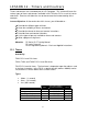
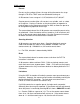
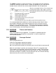
Start a new program and enter the following timer delay circuit.
When developing logic, try to use the words AND and OR, for example …
When X12 AND X13 are on, OR when X14 is on, then timer T0 should
start timing.
TIMERS by default are non-retentive. That means that they do not hold their
value if the input circuit opens. Close the X14 switch and monitor the timer value
(at the bottom of the monitor screen). When X14 opens, notice the timer value
returns to zero.
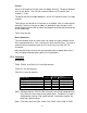
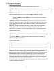
Timers T0~T199 are 100 millisecond timers, T200~T245 are 10 millisecond
timers, for this CPU. The K value is a multiplier. K40 means 40 x 100
milliseconds = 4 seconds. After the timer reaches 40, the T0 contact will close.
Add the following logic.
Turn ON X12 AND X13. When the timer reaches 40 then the T0 contact will
conduct, turning on the output Y1.
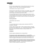
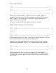
Here is a pulse timer.
When the PLC starts running, the T2 normally closed contact is conducting. This
causes the T2 timer to start counting up to 20 seconds (T2=100msec timer).
When the timer reaches 20 seconds the coil becomes active, which activates the
corresponding contacts. Since this example uses a normally closed contact,
when the coil activates the contact opens, automatically resetting the timer.
When the timer resets, the T2 coil turns off, causing the normally closed contact
to conduct, which starts the timer counting again.
The result is the T2 normally open contact will conduct for 1 ladder scan every 20
seconds creating a timed pulse.