
Programming instructions


58
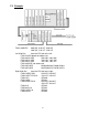
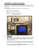
8.2 Indicator Lights
The PLC has indicator LEDs for its inputs and outputs. These lights are on the
right side of the main unit, one set for inputs, one set for outputs. When X0 is
true, LED 0 in the input section is on, when Y0 is one LED 0 in the output section
is on, etc.
There are 4 LEDs on the far right side of the main unit. These are status lights.
• Top light indicates that power is being supplied to the PLC.
• The 2
nd
LED is on when the PLC is in RUN mode, off in STOP mode.
• The 3
rd
light comes on when the battery voltage is low
• The 4
th
LED has 2 purposes
o When blinking indicates there is an error in the program
o When on steady, indicates a CPU problem, such as removing the
memory cassette while the unit was still powered.
8.3 Operator Interface
The exercises we will be doing will involve the use of the GOT as a means of
PLC interface. There are screens loaded in the GOT to simulate discrete I/O,
analog modules, and the various programming exercises planned for this class.
As such, there are no hard-wired inputs and outputs on this trainer. All data
required will be accessible from the GOT terminal screen.
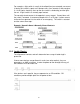
Input Indicators
Output Indicators
Status LEDs